No.
Little Dot is believed to be responsible for some fried tpa3116 chips though. Maybe browse a little for behavior of Little Dot when powering up the Little Dot, maybe sequence is all that needs to be observed.
From the data sheet ABSOLUTE MAXIMUM RATINGS:
"INPL, INNL, INPR, INNR –0.3 to 6.3 V"
If a tube pre-amp on power-up exceeds this value damage may occur...even though there is a capacitor blocking the resting DC level (if any).
This is the preamp I am using. I don't know the input impedance of my DUG board. It is the standard parts that DUG provided. Thanks for helping!
https://www.yuan-jing.com/6n3-6z4-rectifier-vacuum-tube-pre-amplifier-transformer-a
https://www.yuan-jing.com/6n3-6z4-rectifier-vacuum-tube-pre-amplifier-transformer-a
You must be able to find intel online, I don't remember more.
There are several YJ 6n3 versions, 1 tube, 2 tube. Which one adds too much noise and what is gainsetting/inputimpedance of your DUG ?
DUG, this is the only spec available that is in. the manual. Will it be alright to use this as a preamp?
Frequency response: 12 hz~100 Khz (-1dB)
THD+N: 0.15% (80 mW @300 ohm)
Power Output:
350 mW @ 300/600 ohm
300 mW @ 120 oh
100 mW @ 32 ohm
Variable Gain: 3,4,5, or 10x
Recommended Load Impedance: 32 ohm~600 ohm
Input Impedance: 50K ohms
Pre-Amplifier Output Impedance: 600 ohms
Pre-Amplifier Gain: 3-10x (also controlled via gain switches)
Pre-Amplifier Voltage: 10V RMS
Power Consumption: 30W (228V * 0.130A)
Pre-Amplification circuit includes both driver and power tubes
Driver Tubes: 2x GE5654
Power Tubes: 2x Soviet 6H6P
From the data sheet ABSOLUTE MAXIMUM RATINGS:
"INPL, INNL, INPR, INNR –0.3 to 6.3 V"
If a tube pre-amp on power-up exceeds this value damage may occur...even though there is a capacitor blocking the resting DC level (if any).
The gain setting I usually use is the 100K/20K combination resulting in 26dB nominally.
I usually provide the 39K resistor as an option FOR 32dB.
G Gain (BTL)____________min nom max
R1 = 100 kΩ, R2 = 20 kΩ__25__26__27
R1 = 100 kΩ, R2 = 39 kΩ__31__32__33
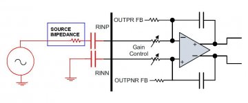
The right half of jpg is the input shown in the data sheet. (page 4)
The left half is an unbalancing of the differential resistor ratios as a result of a source impedance on the (usually) positive input. This can be a pot at mid position or a pre-amp with a high output impedance.
How significant this is I do not know.
I avoid a high impedance source.
As to your question as to whether a tube pre-amp will work the answer is probably yes. Is it the best? IMHO no.")
If you do use a tube pre-amp then I would recommend powering it up then connecting it or power it up with the output shorted until stable DC is established, or put a diode clamping circuit on the signal lines to prevent TPA311x damage. But that is just me.
Whatever you use if you enjoy the sound be happy.
I usually provide the 39K resistor as an option FOR 32dB.
G Gain (BTL)____________min nom max
R1 = 100 kΩ, R2 = 20 kΩ__25__26__27
R1 = 100 kΩ, R2 = 39 kΩ__31__32__33
The right half of jpg is the input shown in the data sheet. (page 4)
The left half is an unbalancing of the differential resistor ratios as a result of a source impedance on the (usually) positive input. This can be a pot at mid position or a pre-amp with a high output impedance.
How significant this is I do not know.
I avoid a high impedance source.
As to your question as to whether a tube pre-amp will work the answer is probably yes. Is it the best? IMHO no.
If you do use a tube pre-amp then I would recommend powering it up then connecting it or power it up with the output shorted until stable DC is established, or put a diode clamping circuit on the signal lines to prevent TPA311x damage. But that is just me.
Whatever you use if you enjoy the sound be happy.
Attachments
DUG,
Thanks for the response. Since I am a schematic challenge and zero knowledge about electronics, the best course for me is to try the tube preamp with my blue yuan-jing TPA 3116 blue board and see what happens. If nothing happen, wouldn't you think it's safe to use in your board?
Thanks for the response. Since I am a schematic challenge and zero knowledge about electronics, the best course for me is to try the tube preamp with my blue yuan-jing TPA 3116 blue board and see what happens. If nothing happen, wouldn't you think it's safe to use in your board?
The gain setting I usually use is the 100K/20K combination resulting in 26dB nominally.
I usually provide the 39K resistor as an option FOR 32dB.
G Gain (BTL)____________min nom max
R1 = 100 kΩ, R2 = 20 kΩ__25__26__27
R1 = 100 kΩ, R2 = 39 kΩ__31__32__33
The right half of jpg is the input shown in the data sheet. (page 4)
The left half is an unbalancing of the differential resistor ratios as a result of a source impedance on the (usually) positive input. This can be a pot at mid position or a pre-amp with a high output impedance.
How significant this is I do not know.
I avoid a high impedance source.
As to your question as to whether a tube pre-amp will work the answer is probably yes. Is it the best? IMHO no.
If you do use a tube pre-amp then I would recommend powering it up then connecting it or power it up with the output shorted until stable DC is established, or put a diode clamping circuit on the signal lines to prevent TPA311x damage. But that is just me.
Whatever you use if you enjoy the sound be happy.
First remove the 100k gainresistors on your DUG's, with preamps you use or goonna use it will only help.
Still to much noise in all volumepot positions? You can change some things on YJ 6N3.
!!!!EDIT: you do have wires from negative inputs to gnd on your DUG's ???
Still to much noise in all volumepot positions? You can change some things on YJ 6N3.
!!!!EDIT: you do have wires from negative inputs to gnd on your DUG's ???
Last edited:
Quick gain question:
I'd like to use the LJM P7 mini as the preamp for this board. This board has a default gain of ~5.5.
I can drop that gain to about 2 by using 5.6k resistors instead of 2.2k.
I was wondering what gain combination I should use. 2 on the preamp + 26 on the TPAs? That seems like a lot.
Thanks!
I'd like to use the LJM P7 mini as the preamp for this board. This board has a default gain of ~5.5.
I can drop that gain to about 2 by using 5.6k resistors instead of 2.2k.
I was wondering what gain combination I should use. 2 on the preamp + 26 on the TPAs? That seems like a lot.
Thanks!
Hi all,
i need your expertise about this amp,
i know first you gona ask me why i have put so much stuff inside like input selector, bluethooth, VU meter.... whitch may of course add some noise!
but i have made few tests by disconnecting all extra stuff to keep only the minimum to run the amp, and what ever i have tryed, i always have this hum or hiss on my speakers.
i have also taken away the grounding, thinking that i could have a ground loop.
so i am open for all suggestion in order to get rid of this hiss which is getting more and more perceptible as i am increasing the volume .
if i turn off or disconnect the source, the hiss intensity is following the volume and very perceptible
thanks in advance
An externally hosted image should be here but it was not working when we last tested it.
An externally hosted image should be here but it was not working when we last tested it.
I connected the shielding to the ground. And yes as tested bore same hum when rising up the volume whithout source!
An externally hosted image should be here but it was not working when we last tested it.
"Rising up volume without source", your problem is just when powered Dugs have open input ?
Some rca's have switch to connect open input to gnd (or resistor to gnd, or resistor capacitor to gnd, or anything, designers choice).
With inputs connected to gnd one should hear 3116 own noise, which is lowest in 20dB setting. In higher gainsettings own noise gets higher but also when inputs aren't to gnd external no signal noise gets amplified more.
In theory (TI writes) and Dug also confirmed, a more distant from Dug pcb negative to gnd connection, could be quieter, in reality it makes a difference, for me never in favour of more distant connection, but that can be a problem I have in any of my setups. In theory a heatsink should be gnd connected, in reality sometimes gnd connection heatsink 3116 contributes to some audible noise.
(For Dugs standoffs aren't connected).
Thanks for the gain structure link irribeo!
Another quick question:
I'm building my DUG-1 board into a case, and to avoid popping on power up/down, I'd like to hook up the front panel switch to the mute pin (with power switch on the back for power on/off).
I've attached the schematic, which has the mute pin on the TPA connected to J2, and the other pin seems to be connected to ground? By default J2 is not populated and thus both pins are floating.
Now I've read elsewhere that in order to mute the circuit, you need to connect the mute pin to VCC. Is that correct? If so, what's the point of GND in J2?
Another detail is that I'd like an LED to indicate when the amp is NOT muted... The LED has a built in resistor for 12vdc input. How can I achieve this?
Thanks!
- Status
- This old topic is closed. If you want to reopen this topic, contact a moderator using the "Report Post" button.
- Home
- Group Buys
- GB for TPA3116/8 PBTL bare pcb