The DUG-1 has power on mute circuitry.
I use a linear supply and the slow falling supply results in very little off pop...more like a small click.
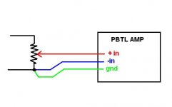
Input lines:
Better like this where green line is shield.
And use a low value of pot if you can. (2K or lower)
I use a linear supply and the slow falling supply results in very little off pop...more like a small click.
Input lines:
Better like this where green line is shield.
And use a low value of pot if you can. (2K or lower)
Attachments
Last edited:
Thanks for the responses irribeo and DUG. I'm still a bit confused.
irribeo, thanks for that info. Makes sense. Looks like J2 is connected to the mute pin.
SDZ looks tied to GND permanently, so now I'm really confused!
1) You mention replacing a diode with the LED. Which diode is that? D6?
2) What is the purpose of J2?
3) How does the built in resistor for 12v supply on the LED factor into the equation?
Thanks guys!
Pot are 50k
Speakers are 92db
Rising up the volume with or without source does the same! Noise is always present!
I'm using the same power supply on the DUG pbtl in a small enclosure, but with I think a 5k or 10k stepped attenuator and 88dB speakers. Small amount of hum/buzz with ear to the speaker. Made it as a gift, so I don't have it nearby to mess with. I did NOT tie my RCA returns to the chassis star ground like you have shown in your pic - I kept the inputs isolated at the rear panel. Do you get a better result with that wire disconnected? Also I can't quite make out how you have your pot pcb wired.
BK
bk856er:
""Do you get a better result with that wire disconnected? ""
no about same or slightly worse
Have you also tried removing that wire that binds all RCA grounds together?
Could you perhaps post a schematic of how your RCAs are wired to the DUG PBTL boards? This is what it looks like to me:
Code:
RCA_1_HOT - red wire - DUG_1_POS_INPUT
RCA_1_GND - clear wire - POWER_EARTH/CHASSIS

RCA_2_HOT - white wire - DUG_1_NEG_INPUT
RCA_2_GND - clear wire - POWER_EARTH/CHASSIS

DUG_1_GND_INPUT - floating
In other words, it looks to me like you have two RCAs going to one PBTL board... but maybe that's just because I can't see how the potentiometer is wired.
My DUG boards, and all my tpa311x boards for that matter, have a very slight hiss that can only be heard with my ear right up next to the speaker. Whenever I'd had worse problems, it's been due to a wiring error on my part.
I suggest going back to basics: take the pot out of the circuit entirely, so you have only amp boards and power supply. Use a smart phone or PC or something (that has builtin volume control) to feed the amp boards directly so you can bypass the pot. You might even want to remove power from one board and test them one at a time. Basically, simplify the build down to the absolute minimum. In such a basic config I would expect no hiss.
Actually, an even simpler test perhaps: have you tried with different input devices? In particular, try an input that runs on battery (smartphone, laptop) to see if that changes things at all.
Maybe another simple test is to attack it from the other end: remove all power to both amp boards, and try something like a 12v battery for just one board. You could probably even use a simple 9v battery for a really quick and easy test.
My hunch is a ground loop of some kind; if you can get your amp running without hiss in one of the above alternate configs, it might help pinpoint the source of the ground loop.
Sly20m, looks like you have some good advice from others, including the board designer, to follow up on.
Can you provide more info or pictures on the pot wiring and input wiring in general?
Also, don't think it matters but you seem to have an extra wire from the SMPS to the star ground (i.e., two green/yellow connections).
Like m_g suggests above and you have already started to do, strip down to basics and bare essentials and see where you stand. Then start adding back your extras.
BK
hi,
thanks all for your time and good advises!
all parts disconnected, i put a 9v battery to power up both dug boards, and cellphone connected straight to dug inputs: boards are dead silent, sound is fine!
if i disconnect the cellphone, so input line open: then i have this hum very load!
then i put back the smps still with cellphone connected straight to input line of dug's boards, and same result : dead silent when no music ! and no audible noise while listening something, but then also when line disconnected (open ) this load hum!
should the dug's board be silent with input line disconnected (open)?
before doing all of that ! tests were performed with a Teac PD-301 as input line.
by putting the song on pause, and rising up the volume , hum noise was there.
sylvain
thanks all for your time and good advises!
all parts disconnected, i put a 9v battery to power up both dug boards, and cellphone connected straight to dug inputs: boards are dead silent, sound is fine!
if i disconnect the cellphone, so input line open: then i have this hum very load!
then i put back the smps still with cellphone connected straight to input line of dug's boards, and same result : dead silent when no music ! and no audible noise while listening something, but then also when line disconnected (open ) this load hum!
should the dug's board be silent with input line disconnected (open)?
before doing all of that ! tests were performed with a Teac PD-301 as input line.
by putting the song on pause, and rising up the volume , hum noise was there.
An externally hosted image should be here but it was not working when we last tested it.
An externally hosted image should be here but it was not working when we last tested it.
An externally hosted image should be here but it was not working when we last tested it.
An externally hosted image should be here but it was not working when we last tested it.
sylvain
For info, I am running these old JMlab Db18, nowadays Focus brand, 92db, 85w max!
Pretty old but still sounding good to me!
Maybe time to change them.
I should invest sometimes anyway, as next project will be this 1st watt m2..
Could it be that these speakers or too sensitive? With the 26db gain set on the board!
Pretty old but still sounding good to me!
Maybe time to change them.
I should invest sometimes anyway, as next project will be this 1st watt m2..
Could it be that these speakers or too sensitive? With the 26db gain set on the board!
Thanks for the pics and additional info, Syl20m.
I can't speak to the DUG since I don't have it nearby, but I normally ignore noise with open inputs. Shorted inputs = no noise = amp is fine at a basic level = focus elsewhere such as wiring and layout. I even have a set of "shorting plugs" that are simply RCA ends with the signal and return connected that I use for setup and testing.
You might try lifting the ground on that input selector and try a single pot for both channels.
Less gain might be helpful in your case (2V input and 92dB speakers).
I also have the M2 and it's one of my favorite amps, but of course a different kettle of fish and also not the quietest if you are super sensitive to that.
Hopefully more knowledgeable folks can provide further guidance.
BK
So I'd like to correctly set the master/slave configuration. I'm keeping 26dB gain, so on one of the boards I'll change the R4/R5 pair from 100k/20k to 75k/47k. I'll also populate C5 and R7 on both boards with 47pF and 4.7k respectively.
1) Do all these values check out?
2) Do I connect both pins of J5 (GND, SYNC) to eachother? I believe the boards have shared ground plane anyway, but maybe twisting the sync wire with gnd is a good thing?
Thanks as always.
1) Do all these values check out?
2) Do I connect both pins of J5 (GND, SYNC) to eachother? I believe the boards have shared ground plane anyway, but maybe twisting the sync wire with gnd is a good thing?
Thanks as always.
Don't forget to set master / slave gain resistors.
I would place the resistor on the master side. This isolated any capacitive loading of the master side. Put the capacitor on the slave side.This will help reduce noise pickup.
Because it is a single board sharing a ground plane, you could connect a thin wire point to point on the bottom of the board...keeping it close to the ground plane. This will help minimize noise pickup.
Attachments
Last edited:
Help on Ticking Noise!
Hi everyone,
I have been enjoying the board so much that it has been my main system until yesterday. After turning on the system, the left channel (mono block) developed a loud ticking sound, while the right channel is working properly. I turned it off immediately. Thinking it could be the interconnect cable, I replaced it. After turning it on again, both channels are now making the ticking sound.
I pulled out the board and its power supply (Astron SL-11A) off the main system and connected it with different speakers, cables, and power supply. Problem still persist. I am now sure the problem is in the board. Perhaps a defective part? Anyone had the same problem?
Hoping to get the group's collective experience and wisdom so I can continue this audio bliss. Thanks a lot!
BTW, parts on the board are all stock, supplied by DUG.
I think the TPA's are dead. Check first for some grounding problem on your audio setup including cables.
That's what I am afraid of. Any idea which part of the board I need to replace?
If the TPA chips are indeed dead, what would cause them to die? From the posted pics, the build looks OK to me (to the extent my untrained eye can make judgments). He's also using a 13.8v PSU, so heat never should have been an issue. I don't recall anyone having a dead TPA chip (excluding dubious quality super cheap overseas stuff and obvious user error issues).I think the TPA's are dead. Check first for some grounding problem on your audio setup including cables.
In case that comes across wrong, I'm not disagreeing! I'm just curious how a TPA chip could be killed in a known good implementation with presumably no fake parts. I've had my two DUG boards running for over two years now without any issue. I leave them powered on 24/7. And they were my first SMD project, so the solder quality is mediocre at best.
Unfortunately, I don't have any ideas. Maybe post some close-up pics of the boards so we can inspect the solder work.
I am quite confident about the solder work as it was done by my brother-in-law who has 30 years of experience soldering electronic components. The board was working fine until it just made ticking noise. BTW, it is not grounded to the chassis due to its material (wood).
Is there a way to test each component as to which is defective or got burnt out?
Is there a way to test each component as to which is defective or got burnt out?
If the TPA chips are indeed dead, what would cause them to die? From the posted pics, the build looks OK to me (to the extent my untrained eye can make judgments). He's also using a 13.8v PSU, so heat never should have been an issue. I don't recall anyone having a dead TPA chip (excluding dubious quality super cheap overseas stuff and obvious user error issues).
In case that comes across wrong, I'm not disagreeing! I'm just curious how a TPA chip could be killed in a known good implementation with presumably no fake parts. I've had my two DUG boards running for over two years now without any issue. I leave them powered on 24/7. And they were my first SMD project, so the solder quality is mediocre at best.
Unfortunately, I don't have any ideas. Maybe post some close-up pics of the boards so we can inspect the solder work.
I am quite confident about the solder work as it was done by my brother-in-law who has 30 years of experience soldering electronic components. The board was working fine until it just made ticking noise. BTW, it is not grounded to the chassis due to its material (wood).
Is there a way to test each component as to which is defective or got burnt out?
Measure the snubber R and R of RC in output filter to check for value shift.
Then try to check for capacitor shorts on the output side of the board.
Are you using two separate supplies?
Thanks for responding, DUG.
Sorry for this dumb question: What is a snubber? Is that the R6 and R7?
I am using one power supply, with two leads (one for each board)
Sorry for this dumb question: What is a snubber? Is that the R6 and R7?
I am using one power supply, with two leads (one for each board)
Measure the snubber R and R of RC in output filter to check for value shift.
Then try to check for capacitor shorts on the output side of the board.
Are you using two separate supplies?
- Status
- This old topic is closed. If you want to reopen this topic, contact a moderator using the "Report Post" button.
- Home
- Group Buys
- GB for TPA3116/8 PBTL bare pcb