Hi all,
Happy owner of the dug-1, I am planing to change my speakers,
I have nowadays some crapp and old Bose that I purchase when I was teenager.
I am going to use this new amplifier in a small room, about 25m2.
I am tempted by the Klipsch RP-160m, and the Cabasse MT32 Antigua , and should give them a try.
I 'll be interesting about your experience if you are running similar size or caracteristics of speakers, or just as user of the dug-1
Thanks
Almost exactly a year ago, I built a power amp for our living room using the DUG-1 tpa3116 boards. See post #410 on page 41 for pics. This amp is still going just fine in the role for which it was intended.
Back after I built that one, I went and grabbed another pair of boards from DUG. Over in the big tpa3116 thread and also the tpa3118 thread, these tiny and cheap "Sanwu" PBTL boards are getting a lot of love. I certainly don't need another amp, but seeing the excitement over those boards put me in the mood to build another amp. And while I could have bought those Sanwu boards and been done with it (and saved some money!), I figured I should make use of the DUG-1 boards I've been sitting on for so long.
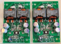
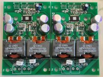
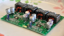
I soldered up the boards this morning (didn't take as long as I expected). This amp will be used on my desktop, so I don't need much power. (In hindsight I wish I'd got the tpa3118 version, which uses the ground plane as a heat sink.) Given the low power requirements, I plan on keeping supply voltage below 15V or so. That allowed me to use 20V 560uF OSCONs for power supply decoupling. And you can see I actually doubled those up. While I'm a huge fan of the ConnexElectronic switch mode power supplies (e.g. SMPS300R), in the interest of doing something different, I'm going to power this amp with an Astron SL-11A (a community favorite).
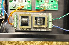
Another little tweak that's easy to see is the use of through-hole film capacitors for the output filter.
The keen observer will notice that where the DC-blocking caps (C2, C3, aka input coupling caps) should be are actually 0-ohm resistors (jumpers). I bought the Edcor TTPC15K/15K transformers a while back, and they've been sitting unused for a long time now. So those will serve for input signal coupling and DC-blocking duty. They'll also convert the single-ended (RCA) input to balanced for input to the DUG-1. I plan on putting a 10k DACT stepped attenuator between the RCAs and the Edcor transformers for volume control.
Just waiting on all the "external" parts to be delivered now: case, RCA jacks, speaker binding posts, attenuator, etc.
Back after I built that one, I went and grabbed another pair of boards from DUG. Over in the big tpa3116 thread and also the tpa3118 thread, these tiny and cheap "Sanwu" PBTL boards are getting a lot of love. I certainly don't need another amp, but seeing the excitement over those boards put me in the mood to build another amp. And while I could have bought those Sanwu boards and been done with it (and saved some money!), I figured I should make use of the DUG-1 boards I've been sitting on for so long.
I soldered up the boards this morning (didn't take as long as I expected). This amp will be used on my desktop, so I don't need much power. (In hindsight I wish I'd got the tpa3118 version, which uses the ground plane as a heat sink.) Given the low power requirements, I plan on keeping supply voltage below 15V or so. That allowed me to use 20V 560uF OSCONs for power supply decoupling. And you can see I actually doubled those up. While I'm a huge fan of the ConnexElectronic switch mode power supplies (e.g. SMPS300R), in the interest of doing something different, I'm going to power this amp with an Astron SL-11A (a community favorite).
Another little tweak that's easy to see is the use of through-hole film capacitors for the output filter.
The keen observer will notice that where the DC-blocking caps (C2, C3, aka input coupling caps) should be are actually 0-ohm resistors (jumpers). I bought the Edcor TTPC15K/15K transformers a while back, and they've been sitting unused for a long time now. So those will serve for input signal coupling and DC-blocking duty. They'll also convert the single-ended (RCA) input to balanced for input to the DUG-1. I plan on putting a 10k DACT stepped attenuator between the RCAs and the Edcor transformers for volume control.
Just waiting on all the "external" parts to be delivered now: case, RCA jacks, speaker binding posts, attenuator, etc.
Attachments
Nearly finished with the build. Did a test run yesterday. Everything works, but there is a "whistling" or "squelching" sound. The squelching is fairly quiet, as it can be mostly drowned out with modest-level music. I didn't measure the level I was playing at, but I'm guessing somewhere in the 65dbA range, and the squealing is definitely lower than that. It sounds like a tea kettle coming to boil (though not nearly as loud) or like the wind howling at night. It's coming out of both channels. It doesn't seem to scale with volume. In this particular test, I was using my smartphone to send the signal to the amp (1/8 stereo to dual RCA).
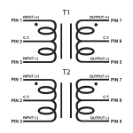
As I mentioned above, I'm using an Edcor TTPC15K/15K for DC-blocking and unbalanced to balanced conversion. Instead of capacitors for C2/C3, I used 0-ohm resistors (jumpers). I attached the schematic of the transformer below.
Here's the (probably naive) wiring I did:
RCA POS to T1 Pin 1
RCA GND to T1 Pin 3
T1 Pin 7 to Amp Input POS (i.e. series with C2)
T1 Pin 6 to Amp Input GND (i.e. series with C3)
T1 Pin 5 to Amp Input NEG
I thought maybe the squelching/squealing/whistling sound might have been due to the RCA-to-transformer side of things (since it was taped in place as a temporary testing measure). But I completely removed everything from the input side of the transformer, and the sound remained.
Based on the little web research I did, I suspect the transformers are microphonic and picking up some noise somewhere... in the big tpa3116 thread, I recall at least one person using transformers (not Edcors, but same idea I think) created some kind of RC snubber circuit. Perhaps such a thing is needed here?
Happy to hear any thoughts or ideas!
Thanks.
Attachments
Last edited:
What's your psu Matt?
I am running 2 Tubecad.com LV regulator kits and an Antek 22V dual secondary transformer and it is dead silent.
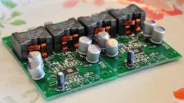
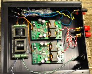
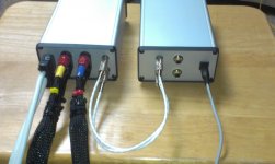
For this build I'm using an Astron SL-11A (linear regulated 13.8V). I suppose it could be the PSU, though in the pics below you can see I've got a decent amount of bulk capacitance (4x5600uF). At moderate levels into 8ohm speakers, this will run for a solid eight seconds after the PSU power is turned off!
I know the wiring could use a little cleanup. I do plan to get some terminal blocks and cut down the excessive wire in the power area.
Attachments
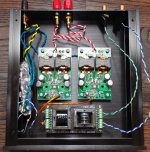
For this build I'm using an Astron SL-11A (linear regulated 13.8V). I suppose it could be the PSU, though in the pics below you can see I've got a decent amount of bulk capacitance (4x5600uF). At moderate levels into 8ohm speakers, this will run for a solid eight seconds after the PSU power is turned off!
I know the wiring could use a little cleanup. I do plan to get some terminal blocks and cut down the excessive wire in the power area.
Power it up with a laptop supply and see if you get a different result...anything below 25v.
Power it up with a laptop supply and see if you get a different result...anything below 25v.
I will give that a try... Those OS-CON caps on the PCBs are actually 20V rated, so I have to be careful not to go too high on PSU voltage. (This was a deliberate design decision, as I intend to use this amp for nearfield/desktop listening, so I'll never need a lot of power.) But I do have a known-good laptop-style Meanwell 15V PSU that I used on one of my previous tpa311x builds.
I can also try the Astron on a known good amp.
I'm also going to cross-post this to the big tpa3116 thread, as this particular thread seems to have few people watching it.
c2 c3 are pos and neg input, not gnd, but I think you misposted and already have it different than written. the sound you hear is same sound when first connecting single ended source to dugs or wiener without neg input shorted to gnd, so there seems to be a gnd missing, maybe you did connect like you wrote ?
c2 c3 are pos and neg input, not gnd, but I think you misposted and already have it different than written. the sound you hear is same sound when first connecting single ended source to dugs or wiener without neg input shorted to gnd, so there seems to be a gnd missing, maybe you did connect like you wrote ?
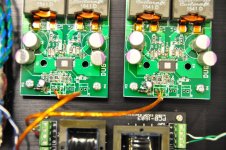
You are right, there is a typo, this is how it's wired:
RCA POS to T1 Pin 1 (solid color wire in pic)
RCA GND to T1 Pin 3 (white/striped wire in pic)
T1 Pin 7 to Amp Input POS (i.e. series with C2, red wire in pic)
T1 Pin 6 to Amp Input GND (green wire in pic)
T1 Pin 5 to Amp Input NEG (i.e. series with C3, yellow wire in pic)
If in doubt, refer to the pictures.
")
So, yeah, I believe GND is shorted to NEG on the RCA side. But my GND on the balanced side (i.e. amp side) is coming off the transformer's center tap (pin 6).
If I short GND to NEG on the balanced (PCB) side, I'm no longer balanced...
I'm finally getting around to this build!
I have some questions:
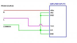
1. I understand J1 is the balanced input signal. How do I use single ended inputs?
2. I understand J2 is for mute. Do I just bridge the two contacts together to mute?
3. I have two DUG-1s on a single PCB (shared ground plane) and I'd like stereo output (so one TPA3116 per channel). Do I need to configure J5 so one channel is the Master and the other is the slave?
Thanks
I have some questions:
1. I understand J1 is the balanced input signal. How do I use single ended inputs?
2. I understand J2 is for mute. Do I just bridge the two contacts together to mute?
3. I have two DUG-1s on a single PCB (shared ground plane) and I'd like stereo output (so one TPA3116 per channel). Do I need to configure J5 so one channel is the Master and the other is the slave?
Thanks
I'm finally getting around to this build!
I have some questions:
1. I understand J1 is the balanced input signal. How do I use single ended inputs?
2. I understand J2 is for mute. Do I just bridge the two contacts together to mute?
3. I have two DUG-1s on a single PCB (shared ground plane) and I'd like stereo output (so one TPA3116 per channel). Do I need to configure J5 so one channel is the Master and the other is the slave?
Thanks
1. see jpg 1, 2
2. from the data sheet:
"Mute signal for fast disable/enable of outputs (HIGH = outputs Hi-Z, LOW = outputs enabled). TTL logic levels with compliance to AVCC."
3. You can configure as master/slave if you want. I haven't in my home stereo. Seems to work OK. If you want to then remember that the values in the data sheet are wrong. The correct values are much lower. look here:
http://www.diyaudio.com/forums/group-buys/257996-gb-tpa3116-8-pbtl-bare-pcb-37.html#post4159967 for that discussion.
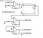
Also a note about question 1.
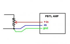
IMHO this amp is better suited to be driven by a low impedance source. There has been much gnashing of teeth over noise issues when using pots/transformers, etc.
I use a buffer and drive + and - inputs (preamp.jpg) from a separate box...no noise.
Hope that helps.
Attachments
Thanks for the reply and info DUG!
My plan was to use a SMPS300RS supply I have configured at 22 volts out.
I was also planning ordering a LJM P7 Mini (with a swap-in LM4562 op amp), powered by the +/- 15VDC auxiliary supply from the SMPS.
Volume control will be in the preamp stage.
1. Would you say the P7 Mini is a good match? I'm not sure of its output impedance.
2. I'm also not sure how to bypass the AC rectification circuitry on the P7 Mini to feed the regulators directly with 15vdc. Any pointers? PCB Image here
3. On the mute pin: Sorry to be slow, but I'm not sure what "TTL logic levels with compliance to AVCC" means. Looking at SCHEMATIC1 _ 04-Aug-2014.pdf, what is the purpose of each pin on the J2 connector?
4. You included some SMD resistors in a packet stuck to the PCB. What are these for?
Thanks again!
Chris
Thanks for the reply and info DUG!
My plan was to use a SMPS300RS supply I have configured at 22 volts out.
I was also planning ordering a LJM P7 Mini (with a swap-in LM4562 op amp), powered by the +/- 15VDC auxiliary supply from the SMPS.
Volume control will be in the preamp stage.
1. Would you say the P7 Mini is a good match? I'm not sure of its output impedance.
2. I'm also not sure how to bypass the AC rectification circuitry on the P7 Mini to feed the regulators directly with 15vdc. Any pointers? PCB Image here
3. On the mute pin: Sorry to be slow, but I'm not sure what "TTL logic levels with compliance to AVCC" means. Looking at SCHEMATIC1 _ 04-Aug-2014.pdf, what is the purpose of each pin on the J2 connector?
4. You included some SMD resistors in a packet stuck to the PCB. What are these for?
Thanks again!
Chris
LM4562 looks OK.
1. It looks like the P7 mini would work as a low impedance buffer...this is what you want for a single ended drive...use pix 1 or 2 in previous post.
2. You can install the bridge rectifier and feed the AC input with +/- 15 (16 Minimum would be better) the diode bridge will "direct" the supplies to the correct polarity and the LM7812/LM7912 will regulate to the required +/-12V for the amp. Watch out for ground loops. It would be better if the +/-15V was isolated from the rest of the circuitry (22V) and connected only via signal lines to the amp input terminals.
3. Do not switch it above your 22V.
4. Probably for changing the gain of the amplifier...see data sheet page 6.
Thanks again for the help DUG.
I'll look deeper into the datasheet for more info on master/slave config.
> 2. You can install the bridge rectifier and feed the AC input with +/- 15 (16 Minimum would be better) the diode bridge will "direct" the supplies to the correct polarity and the LM7812/LM7912 will regulate to the required +/-12V for the amp. Watch out for ground loops. It would be better if the +/-15V was isolated from the rest of the circuitry (22V) and connected only via signal lines to the amp input terminals.
1. Is this preferable to just omitting the bridge rectifier and feeding the regulators with DC directly?
2. I understand the TPA3116 shouldn't be powered up without a speaker load. Is there any way around this?
3. Would you advise using a speaker protection board?
Have a good weekend!
Thanks again for the help DUG.
I'll look deeper into the datasheet for more info on master/slave config.
> 2. You can install the bridge rectifier and feed the AC input with +/- 15 (16 Minimum would be better) the diode bridge will "direct" the supplies to the correct polarity and the LM7812/LM7912 will regulate to the required +/-12V for the amp. Watch out for ground loops. It would be better if the +/-15V was isolated from the rest of the circuitry (22V) and connected only via signal lines to the amp input terminals.
1. Is this preferable to just omitting the bridge rectifier and feeding the regulators with DC directly?
2. I understand the TPA3116 shouldn't be powered up without a speaker load. Is there any way around this?
3. Would you advise using a speaker protection board?
Have a good weekend!
1. If you can bypass the bridge and feed the regulators directly this would be better...(make sure the polarity is correct)
2. No, you need some load...8R-10R or any small speaker.
3. The IC has DC protection and current limit built in...anything beyond that is your preference...remember the amp needs a load if you switch out the speaker.
Is Class D considered to be a DC or direct coupled amplifier?
Sorry for this newbie question.
I recently acquired a headphone tube amplifier with preamp output (Little Dot MKIII). I plan to use this device for my DUG's amplifier to control volume. According to the manufacturer, the headphone amp cannot used as a preamp for DC or direct coupled amplifier. Is DUG's board considered to be one?
Thanks!!!!
Any particular behavior that you know of that I should be watching for? I have been using a Yuan-Jing 6N3 tube preamp but there's noise in the speaker. Thanks.
No.
Little Dot is believed to be responsible for some fried tpa3116 chips though. Maybe browse a little for behavior of Little Dot when powering up the Little Dot, maybe sequence is all that needs to be observed.
- Status
- This old topic is closed. If you want to reopen this topic, contact a moderator using the "Report Post" button.
- Home
- Group Buys
- GB for TPA3116/8 PBTL bare pcb