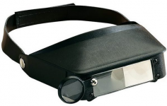
I normally use this for this kind of work.
It's got two selectable magnifications plus the round lens. I rarely use the round lens though.
If space permits, I prefer to use my Mantis Vision microscope. But for this, where the PCB is mounted in the chassis, the limited space makes the headband magnifier easier to use. Even i Denmark they cost less than the equivalent of USD 10.
Attachments
Hi Jens,
I will keep my eyes open for one of those. I really need it these days. If I can find them online, I'll buy a set right now.
So, I installed the modification to the best of my abilities. It looks properly installed, but doesn't work properly. No smoke that I can see, but the peak light will come on in the -20dB position of the input attenuator. I was really hoping to avoid sending it back in due to the trouble and expense of getting it here in the first place. I had the most trouble with lead-free solder, so I switched to 63/37 normal solder. The hookup wire was next to invisible, so I resorted to soldering the tiny bright spot (wire end tinned) to the location and inspected the work with a magnifying glass. Everything looks okay, but it obviously isn't.
Are those resistors 603 size by chance? I can work with 805 and up, but those are just a bit too small. I did remove them okay, no dramatics there. I was using a small tip on the iron, which is why the lead-free solder was giving me a hard time.
The PCBs are attached to the chips (TL084) with a dab of silicone, and the same for the long wires. Tape tends to come off in time. A sharp blade will release the PCB and wires if the need arises.
One thing I had zero problem with where the instructions. Everything was very clear and well laid out. Someone did a good job on that. Now to find those goggles!
-Chris (blind old technician)
You can of course still get overload/overflow. If you set it to the -20 dBV position, a sine wave signal above 100 mV will give you an overflow.
The add-on board is related to the overvoltage protection, which is something entirely different.
The way I normally test the overvoltage protection and modification is as follows:
Set the input attenuator to the 10 dBV setting.
Set the inputs to DC (not AC).
Take a lab power supply or similar and set it to around 10 V.
Connect a 1 k resistor in series with one of the supply leads (just in case something should be wrong).
Connect the wires, with the resistor in series, between chassis (e.g. the 4 mm plug) and (one at a time):
Pin 2 of the XLR input left
Pin 3 of the XLR input left
Pin 2 of the XLR input right
Pin 3 of the XLR input right
Check that you can hear a relay clicking in the analyzer each time you connect to an input pin.
Repeat for the opposite polarity.
Now set the inputs to the 20 dBV range.
Repeat the tests above and check that no relays are clicking
If this is OK you could test it further by:
Setting the inputs to the 30 dBV range.
Apply a signal of e.g. 20 V rms balanced to each input. The distortion should be low (at least if you are using a low distortion generator") ). I normally use a Stanford Research DS360 and get THD levels of around - 112 to -114 dB.
). I normally use a Stanford Research DS360 and get THD levels of around - 112 to -114 dB.
If you don't have a balanced source, you could also apply a level of 10 Vrms to each of the input signal pins (2 and 3, one at a time) for each channel.
If the modification has not been done, you will see increased distortion when you get above around 6 - 7 Vrms.
The add-on board is related to the overvoltage protection, which is something entirely different.
The way I normally test the overvoltage protection and modification is as follows:
Set the input attenuator to the 10 dBV setting.
Set the inputs to DC (not AC).
Take a lab power supply or similar and set it to around 10 V.
Connect a 1 k resistor in series with one of the supply leads (just in case something should be wrong).
Connect the wires, with the resistor in series, between chassis (e.g. the 4 mm plug) and (one at a time):
Pin 2 of the XLR input left
Pin 3 of the XLR input left
Pin 2 of the XLR input right
Pin 3 of the XLR input right
Check that you can hear a relay clicking in the analyzer each time you connect to an input pin.
Repeat for the opposite polarity.
Now set the inputs to the 20 dBV range.
Repeat the tests above and check that no relays are clicking
If this is OK you could test it further by:
Setting the inputs to the 30 dBV range.
Apply a signal of e.g. 20 V rms balanced to each input. The distortion should be low (at least if you are using a low distortion generator
). I normally use a Stanford Research DS360 and get THD levels of around - 112 to -114 dB. If you don't have a balanced source, you could also apply a level of 10 Vrms to each of the input signal pins (2 and 3, one at a time) for each channel.
If the modification has not been done, you will see increased distortion when you get above around 6 - 7 Vrms.
I normally use this for this kind of work.
It's got two selectable magnifications plus the round lens. I rarely use the round lens though.
If space permits, I prefer to use my Mantis Vision microscope. But for this, where the PCB is mounted in the chassis, the limited space makes the headband magnifier easier to use. Even i Denmark they cost less than the equivalent of USD 10.
This works really well for the cost:
Amazon.com : Rightwell LED Illuminated Hands Free Head Magnifier Visor 1.0X to 3.5X Zoom with 5 Detachable Lenses - Head Mounted Lighted Magnifying Glasses for Reading, Jewellery Loupe, Watch and Electronic Repair : Office Products
I agree, I am buying this to replace another piece of test equipment which I use to test my reworked Phase Linear Amps. Is anybody doing any REAL work???? I DIY it also.
Working under a limited budget and "Doing the Best they can" has nothing to do with real work..... Real work earns me money to pay my credit card bill....
Working under a limited budget and "Doing the Best they can" has nothing to do with real work..... Real work earns me money to pay my credit card bill....
Last edited:
What do you mean by real work? This is a DIY forum, aren’t everyone trying to do the best work they can under a limited budget?
Real Work := testing real DUT’s; distortion, noise, dynamic range, you know the basic 6 tests as opposed to picking the fly poop out of the pepper on the noise floor.
DT
let's test something real!
Real Work := testing real DUT’s; distortion, noise, dynamic range, you know the basic 6 tests as opposed to picking the fly poop out of the pepper on the noise floor.
DT
let's test something real!
Why would someone buy this and just do noise floor testing. I am sure people are just making sure want the device performance is before real testing is done to distinguish DUT vs test equipment.
Hi Jens,
I bought a couple magnification visors for bench work. One from Amazon, the other (looks better maybe) from Ebay.
I am using ARTA for control and display.
Doing loop-back tests with the source switched to 10 volts and -7 dBFS, the left channel is working fantastically well (showing 0.00014% harmonics), the right channel is showing a spray of harmonics (showing 0.0088% harmonics). The receivers are both set to 10V. No overload lights showing.
Switching the input ranges, L shows overload at 3.16 V while R doesn't show any overload until you hit 100mV. Swapping the L and R channels shows the exact same behavior, so the issue appears to be with the R channel input circuit. I'll have to have another look at my work.
Looking at the unit the way you describe, I get the following results:
Pin 2 of the XLR input left - nothing
Pin 3 of the XLR input left - nothing
Pin 2 of the XLR input right - nothing
Pin 3 of the XLR input right - Click + OVF flash
Repeat for the opposite polarity. - nothing, no response at all
10V range
Pin 2 of the XLR input left - Click + OVF flash
Pin 3 of the XLR input left - Click + OVF flash
Pin 2 of the XLR input right - nothing
Pin 3 of the XLR input right - Click + OVF flash
Repeat for the opposite polarity. - nothing, no response at all.
I didn't check at 30 V, I'll do that once I have an amplifier connected. I think this is probably enough information to locate the problem for now.
Hopefully this helps.
-Chris
I bought a couple magnification visors for bench work. One from Amazon, the other (looks better maybe) from Ebay.
I am using ARTA for control and display.
Doing loop-back tests with the source switched to 10 volts and -7 dBFS, the left channel is working fantastically well (showing 0.00014% harmonics), the right channel is showing a spray of harmonics (showing 0.0088% harmonics). The receivers are both set to 10V. No overload lights showing.
Switching the input ranges, L shows overload at 3.16 V while R doesn't show any overload until you hit 100mV. Swapping the L and R channels shows the exact same behavior, so the issue appears to be with the R channel input circuit. I'll have to have another look at my work.
Looking at the unit the way you describe, I get the following results:
20 V rangeSet the input attenuator to the 10 dBV setting.
Set the inputs to DC (not AC).
Take a lab power supply or similar and set it to around 10 V.
Connect a 1 k resistor in series with one of the supply leads (just in case something should be wrong).
Connect the wires, with the resistor in series, between chassis (e.g. the 4 mm plug) and (one at a time):
Pin 2 of the XLR input left - nothing
Pin 3 of the XLR input left - nothing
Pin 2 of the XLR input right - nothing
Pin 3 of the XLR input right - Click + OVF flash
Repeat for the opposite polarity. - nothing, no response at all
10V range
Pin 2 of the XLR input left - Click + OVF flash
Pin 3 of the XLR input left - Click + OVF flash
Pin 2 of the XLR input right - nothing
Pin 3 of the XLR input right - Click + OVF flash
Repeat for the opposite polarity. - nothing, no response at all.
I didn't check at 30 V, I'll do that once I have an amplifier connected. I think this is probably enough information to locate the problem for now.
Hopefully this helps.
-Chris
Hi soongsc,
I can't imagine anyone dropping $1,500 Canadian for this who won't be using it daily. At least I will be using it every single day. Some of you might only use it weekly, but when you do, the tests will be important.
-Chris
I agree.Why would someone buy this and just do noise floor testing. I am sure people are just making sure want the device performance is before real testing is done to distinguish DUT vs test equipment.
I can't imagine anyone dropping $1,500 Canadian for this who won't be using it daily. At least I will be using it every single day. Some of you might only use it weekly, but when you do, the tests will be important.
-Chris
Working now
Hi Jens,
Okay, I found two leads had detached from the pads. I used hemostats to hold the wire and they crimped them. The wires broke right at the crimps. The others had fallen off before I got them soldered down.
I also found two bridged connections. Having tired eyes didn't help, but a fresh look today and some suspicion lead me to the problems. Removed all the solder and had a fresh go. So those were the final two issues.
Now I will clean off the flux (looks ugly in the pictures). Then test it again before buttoning it up again. I used the flux to keep the solder on the pads. Without it the solder was perfectly happy to string out across the board following the tip.
These pictures tell the entire gory tale as they are before shots.
Thanks Jens, the problem was where it had to be. You made me look earlier in the day while I was still almost sharp.
So this 6001 is all working properly both in loopback tests and your tests. I did notice that the protection seems to be insensitive to the negative polarities. Both channels are the same that way.
-Chris
Attachments
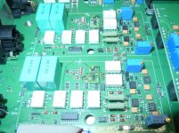
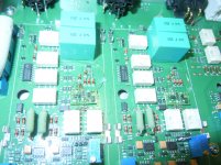
The protection should work for both polarities. Otherwise there is something wrong.
The pictures area bit blurry, but please check the solder point (on the mod PCB) closest to the attenuator resistors (the 1206 resistors on the Main Board) and how it is connected to the Main Board.
The pictures area bit blurry, but please check the solder point (on the mod PCB) closest to the attenuator resistors (the 1206 resistors on the Main Board) and how it is connected to the Main Board.
- Status
- Not open for further replies.
- Home
- Group Buys
- GB for RTX6001 Audio Analyzer with AK5394A and AK4490