Member
Joined 2009
Paid Member
I'm not convinced that the White cathode follower by itself doesn't extend the performance to allow lower q current with good clipping behaviour - but the Taylor follower that you have here (parts of which are labeled in other posts as Elvee Fix) does just that if I am understanding correctly the description on tube cad by Broskie.
Taylor Source Follower
Yeah, Taylor thats the one! I had no idea such a thing...
Started out in my mind WCF, but with PSRR so awful it was useless.
Elvee's PSRR fix turns my paraphase splitter from WCF to a Taylor.
Damn hard to come up with anything original these days...
I still think JLH enhanced by WCF/Taylor in one circuit might be unique.
Even if I didn't know what the heck exactly it was, I knew it had to be
something very special. And I would have abandoned it if not for Elvee.
I had no clue how PSRR might be fixable in any reasonable part count.
I still look at that splitter and think Concertina, but its a subtractive
splitter (subtract from constant at the base). Not something you see
every day.
Member
Joined 2009
Paid Member
I suppose that everyone has read the original article:
http://www.tcaas.btinternet.co.uk/jlh1969.pdf
Also the PLH follower has been discussed before at pass labs:
http://www.diyaudio.com/forums/pass-labs/140740-plh-zero-nfb.html
Kenpeter,
Your Taylor applicated JLH-follower(or whatever we might call it) seems to be more low distortion than a std JLH follower. Can we suspect this is due to some added feedback from the white/taylor topology? It should also have lower Zout.
Member
Joined 2009
Paid Member
I'm primarily looking at simple Follower so I am looking at the basic Taylor Follower as already implemented above and I am looking at the JLH follower separately. I had not merged them together as shown in this thread - mostly because I didn't think of it and now I didn't do it because I don't want to 'steal somebody else's thunder' ") I can't post my circuit from here at this time (I'm at work).
I can't post my circuit from here at this time (I'm at work).
I'm planning to build it with BJT outputs based on 2SA1943/2SC5200.
My plan is that once I have set up a simple follower I can then play with some front end variations - some very simple things, nothing new to this forum but new to me !
In simulations the Taylor follower has higher distortion (H2) than the JLH follower. I believe the JLH follower is superior in this regard and it's PSRR is also very good if not better than the Taylor follower. I will probably stick to something simple rather than a combination..BUT this thread has certainly whetted my appetite for such a thing so I have started to play with it in my sims.
I have some power start up worries, as I'm not sure that I will have any protection relays on the output or a Cap multiplier on the psu. With the little work I've done in the simulation it seems that the Taylor solution needs care in this regard because when that transistor turns on it does so pretty quickly and that pops the output device on pretty quickly too.
Thermal runaway with BJT outputs is another concern and the current fed to the output via the Taylor transistor needs to be set up with a balancing thermal dependency by mounting one of the CCS devices on or near the main heatsink.
I can't post my circuit from here at this time (I'm at work).I'm planning to build it with BJT outputs based on 2SA1943/2SC5200.
My plan is that once I have set up a simple follower I can then play with some front end variations - some very simple things, nothing new to this forum but new to me !
In simulations the Taylor follower has higher distortion (H2) than the JLH follower. I believe the JLH follower is superior in this regard and it's PSRR is also very good if not better than the Taylor follower. I will probably stick to something simple rather than a combination..BUT this thread has certainly whetted my appetite for such a thing so I have started to play with it in my sims.
I have some power start up worries, as I'm not sure that I will have any protection relays on the output or a Cap multiplier on the psu. With the little work I've done in the simulation it seems that the Taylor solution needs care in this regard because when that transistor turns on it does so pretty quickly and that pops the output device on pretty quickly too.
Thermal runaway with BJT outputs is another concern and the current fed to the output via the Taylor transistor needs to be set up with a balancing thermal dependency by mounting one of the CCS devices on or near the main heatsink.
Last edited:
Something more to chew on...
I've realized the Taylor/WCF circuit is really MJK's Anti-Triode totem turned
inside out! So you can abuse the same stOOpid AB pet tricks with Schottky
shaping diodes. Its hyperbolic A, not AB, but you know what I'm driving at.
Extreme opposite of JLH misbehavior, way too much bias in the center...
You know, because it an Anti-complimentary follwer on the flip side, you
ain't never gonna get rid of 2nd hamonic merely by the SRPP transistor
appears to offer a compliment... The "anti" transistor behavior is shaped
by external maths more than its own curve. Insultramentary architecture...
Anyways, if you want to get rid the 2nd harmonic, just get rid of all of em.
Fix an emitter's current, and you fix its voltage drop. Make the "anti" do all
the grunt work, so the one doing the follower function is prevented from
experiencing current variations. I can nail -120db 2nd -140db 3rd in full
Taylor mode. Though its not particularly power efficient to do so.... Its
sorta like an emitter follower with a CCS. Except the emitter never sees
any load current variations either, thinks load is much higher impedance.
But my drawings today are about HyperA, not full Taylor.
I probably only confuse things by talking about both in one post...
Attachments
Anyways, if you want to get rid the 2nd harmonic, just get rid of all of em.
I agree
Member
Joined 2009
Paid Member
Extreme opposite of JLH misbehavior, way too much bias in the center...
I don't understand what this means
I can nail -120db 2nd -140db 3rd in full
Taylor mode. Though its not particularly power efficient to do so....
As far as I can see, this is well beyond what the front end is capable of doing, so do you think the tradeoffs (you mention power efficiency) are small enough to ignore ?
If you can put one of these distortionless A's in parallel with an AB, B, or D....
Either open loop, or as a current dumper... Yeah, then maybe the wastefully
biased Taylor stage wouldn't need so much Iq as to carry the full load by itself.
-------------------
What's not to understand about JLH overbias in the center? The sum of two
base currents is held to a constant under all conditions. But the base currents
needed for full output current swing are much higher than required for normal
class A quiescence. JLH has nowhere to dump this excess of quiescent base
current when it isn't needed, so output transistors idle hotter than necessary...
In my most recent schematic, Q4 is the shunt that bleeds off those excess
drive currents. Is also why it doesn't need a constant current source, drive
currents are shunt regulated instead....
OOpss.. I got it backwards. Q4 is a modulated current source, not a shunt...
Been looking at this thing standing on my head too much.
Last edited:
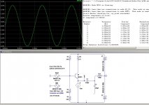
This is a power JFET version of the Taylor follower, with the JFET biased in Triode mode. 5 transistors, because we need 2 extra for the triode mode cascode. Great sound, according to the few who have built it.
http://www.diyaudio.com/forums/pass...urce-follower-configurations.html#post1603771
And you can increase the bias to 1.3A as Nelson Pass did in his Zen V9 for use as power amp. But you probably need to change the values for the Taylor branch to adapt to the increased bias and lower Zout, etc.
Patrick
Member
Joined 2009
Paid Member
If you can put one of these distortionless A's in parallel with an AB, B, or D....
Either open loop, or as a current dumper... Yeah, then maybe the wastefully
biased Taylor stage wouldn't need so much Iq as to carry the full load by itself.
-------------------
What's not to understand about JLH overbias in the center? The sum of two
base currents is held to a constant under all conditions. But the base currents
needed for full output current swing are much higher than required for normal
class A quiescence. JLH has nowhere to dump this excess of quiescent base
current when it isn't needed, so output transistors idle hotter than necessary...
In my most recent schematic, Q4 is the shunt that bleeds off those excess
drive currents. Is also why it doesn't need a constant current source, drive
currents are shunt regulated instead....
OOpss.. I got it backwards. Q4 is a modulated current source, not a shunt...
Been looking at this thing standing on my head too much.
I don't really understand still - you need to give me a better explanation.
First off, in terms of religious convictions, I don't think of BJTs as current devices. They are voltage controlled devices. The have a base current, but that's a feature of their input impedance. In reality the base currents won't match because the input impedances will be different, the hfe will not be exactly the same and temperatures may not the the same.
If the currents through both devices total up to the same then the voltage drop across base-emitter is the same for both devices (roughly). This isn't a symmetrical circuit so one device is the 'master' and the other is the 'slave'. The 'master' device sets the q-current through the output pair and it's base is driven from the collector of the JLH phase splitting device. The other output device is the 'slave' and it Follows the output, roughly two 'Vbe drops' below the drive signal (one from the JLH phase splitting device, the other the output device it'self).
You'll need to help me here.
Lastly, I don't see why this is bad, why is it inefficient "in the middle", it's Class A afterall
Last edited:
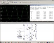
I don't have an oscillation problem. However, it doesn't bring any improvement either: distortion stays stuck at 2.2ppm.Taylor only hides emitter distortion, does nothing to fix the Early effect.
But every time I try to wrap Taylor around a cascode... LTSpice breaks
into wild oscillations.
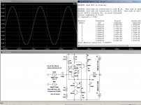
Bootstrapping the collector of Q1 looks much more promising: distortion now drops to 70ppb (I hope in a month's time, we'll be talking in ppt).
Attachments
Last edited:
I don't have an oscillation problem. However, it doesn't bring any improvement either: distortion stays stuck at 2.2ppm.
Bootstrapping the collector of Q1 looks much more promising: distortion now drops to 70ppb (I hope in a month's time, we'll be talking in ppt).
Q1 was the Early I meant to cascode away, the comparator is what matters.
I don't know how much matters having another cascode in the taylor circuit?
I abused a JFET rather than C2 to lift the base of the cascoding transistor in
my attempts that broke into oscillation.
Last edited:
I don't really understand still - you need to give me a better explanation. You'll need to help me here.
Lastly, I don't see why this is bad, why is it inefficient "in the middle", it's Class A afterall
Yes, JLH is an A. But lets be clear, its not your "normal" class A.
Normal A holds the output current sum a constant under all conditions.
JLH quiescent is HIGHER than purely linear class A. Because the bases require
a non-linear current input for a linear current output. But total base current
is held constant, at value required to swing peaks. The result is like HyperA,
but JLH nonlinearity bent entirely the wrong way (for idle power efficiency).
The sum of output currents is NOT a constant, but higher in the middle.
As long as you got Watts to burn, and don't mind efficiency worse than A...
Its not a problem.
Last edited:
Member
Joined 2009
Paid Member
I think I'm going to have study it a bit more. I understood only as far as the case that a SE output with a CCS load will keep a constant current through the output (nice for the psu) but the difference between the JLH A and a 'normal' A is still needing some thought.
Revintage - your ideas are the final shove needed to get me going with my own project. I've opened up a separate thread not to abuse this one because it's focus is on Ken's Diamond (like that name).
Looking at Ken's diamond I'm interpreting it differently now. It looks like the JLH follower where the phase splitting device has a modulated emitter load - flavours of Aleph distortion reduction perhaps. I may look at my own JLH from this perspective to see if anything makes sense ?
- Status
- This old topic is closed. If you want to reopen this topic, contact a moderator using the "Report Post" button.
- Home
- Amplifiers
- Solid State
- four transistor emitter follower (diamond buffer) as power output stage?