I have recently built an amplifier with output stage what is called here "diamond buffer", using FETs. I was sure this was not a new output FET concept although have never seen it before. I expanded my observations in the thread named {My 'parallel' amplifier}. I switched to another amplifier since then but plan to return to that one as soon as get good acoustic systems for listening (measured parameters were not that bad).
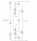
here is output stage of amplifier that was proposed around 1987 in 'Radio' magazine. It was entitled 'parallel' there that is where I took this name from.
I could mess base resistors value a little bit though (drawn without book). That amplifier was intended to drive 8 or 4 Ohm load.
I could mess base resistors value a little bit though (drawn without book). That amplifier was intended to drive 8 or 4 Ohm load.
Attachments
"djk, I've been messing around with this for a while. I'd like to read your posted links, but they are dead. Anything you can point me to?"
http://www.audiodesignguide.com/my/Cool_Follower1.GIF
http://www.audiodesignguide.com/my/Hot_Follower1.GIF
http://www.audiodesignguide.com/index_nobanner.html
Nice DC servo:
http://www.tnt-audio.com/gif/a18a.gif
http://www.audiodesignguide.com/my/Cool_Follower1.GIF
http://www.audiodesignguide.com/my/Hot_Follower1.GIF
http://www.audiodesignguide.com/index_nobanner.html
Nice DC servo:
http://www.tnt-audio.com/gif/a18a.gif
I have open a new thread, using Marc Vi's sziklai-darlington
output stage instead of normal diamond buffer's NPN/PNP, so the
6-transistor output stage can be an huge AC current gain.
sziklai-darlington diamond buffer (SDDB) for power output stages
ULTIMA-SDDB CLASS-A POWER AMP CIRCUIT PDF
In this SDDB POWER AMP , the Vbe of Q13 about 0.7V is equal to
the stand-by current multiply (R25//R33+R26//R34), if R25//R33=
0.33 OHM, the stand-by current will be 0.7V/(0.33+0.33)=1.06A.
It is about a small power class-A amp's stand-by current .
It can be applied to either Class-A or Class-AB.
lumanauw said:Hi, Wrenchone,
How much bias do you put in your amp? Will this DB works properly if the bias in the final stage only about 25mA?
You can read my mind. I'm thinking about using this output stage with no-global feedback frontend.
I think of 2 candidates that can do this. One is this DB, and the other is Hawks ford EC or NP-PMA by PMA. I think both can be driven without global NFB, but I still don't know which one is better.
This Buffer is intended for headphones in the 50-600 ohm range. The Schematic referenced to was my first attempt at error correction and the buffer as shown worked splendidly however what ever voltage was dropped across the 100 ohm resistors in the voltage divider was that much less voltages swing available than a conventional Diamond buffer. This also was dependent upon Bias current. As illustrated this is only 200-600Mv. Since this is a resistive divider as opposed to a more elegant voltage reference and current source the current will change thought these resistors making large signal swings clip earlier than expected in actual operation. This voltage divider is needed to maintain enough Vce on the driver transistors to sty turned on .If the collectors were connected to the opsing out transistors emitter only about 200-200 mV of VCE is maintained across the drivers. This as one would expect would have some strange stability issues and one would be correct as I have had this circuit do everything from reproducing actuate musical sounds to a perfect white nose generator. However once the Bias is adjusted and a stable input output connection is maintained it remains stable and works thereafter.
As a stand-alone unity gain feedback free Line or headphone driver this circuit’s high input impedance and symmetrical input bias currents make DC offset stable with in +/- 2 mV with source resistances from 100 to 50,000 Ohms. Most BJT Input op amps with lots of Feedback are nowhere near that precise unless input bias current compensation is used. The THD still measures superb on this buffer as shown @ 2 volts and 32 ohm real Headphones not a pure resistor as typically used.
OOps the White trace is the Sound card only the Green the Buffers open loop into Sony MDR-V700 Dj
Attachments
Alme last posted on DIYAudio.com in august of last year, so he's not likely to reply.
C1 and C2 are bootstrap capacitors, in short, they make the resistors look like constant current sources with a compliance voltage reaching into the negative. Try to analyze it thinking of the capacitors as voltage sources.
You should google "Bootstrap capacitor".
C1 and C2 are bootstrap capacitors, in short, they make the resistors look like constant current sources with a compliance voltage reaching into the negative. Try to analyze it thinking of the capacitors as voltage sources.
You should google "Bootstrap capacitor".
ppl said:lumanauw said:Hi, Wrenchone,
How much bias do you put in your amp? Will this DB works properly if the bias in the final stage only about 25mA?
I think of 2 candidates that can do this. One is this DB, and the other is Hawks ford EC or NP-PMA by PMA. I think both can be driven without global NFB, but I still don't know which one is better.
This Buffer is intended for headphones in the 50-600 ohm range. The Schematic referenced to was my first attempt at error correction and the buffer as shown worked splendidly however what ever voltage was dropped across the 100 ohm resistors in the voltage divider was that much less voltages swing available than a conventional Diamond buffer. This also was dependent upon Bias current. As illustrated this is only 200-600Mv. Since this is a resistive divider as opposed to a more elegant voltage reference and current source the current will change thought these resistors making large signal swings clip earlier than expected in actual operation. This voltage divider is needed to maintain enough Vce on the driver transistors to sty turned on .If the collectors were connected to the opsing out transistors emitter only about 200-200 mV of VCE is maintained across the drivers. This as one would expect would have some strange stability issues and one would be correct as I have had this circuit do everything from reproducing actuate musical sounds to a perfect white nose generator. However once the Bias is adjusted and a stable input output connection is maintained it remains stable and works thereafter.
As a stand-alone unity gain feedback free Line or headphone driver this circuit’s high input impedance and symmetrical input bias currents make DC offset stable with in +/- 2 mV with source resistances from 100 to 50,000 Ohms. Most BJT Input op amps with lots of Feedback are nowhere near that precise unless input bias current compensation is used. The THD still measures superb on this buffer as shown @ 2 volts and 32 ohm real Headphones not a pure resistor as typically used.
OOps the White trace is the Sound card only the Green the Buffers open loop into Sony MDR-V700 Dj
What post are you replying to? And what is the references schematic?
Hello WoW what a Blast from the past. The Schematic i am refering to is from this
It has been quite some time since this topic has been brought up and now that it has I am pleased to report that My Dynamically Bias Diamond Buffer for Headphone amplification has been designed and working great see attachment. This configuration has a silky smooth almost floating in a 3d holograph midrange to Die for compared to the classic Walt Jung implementation and measurably lower THD when driving the same 300 ohm Real world Headphone as a load. Both Diamond buffer topologies were Biased the same at 25 mA and used the same Emitter resistor value and ratios as the classic diamond buffer I am very happy with the sound quality and stability as used in the PPA Headphone amp. http://tangentsoft.net/audio/ppa/amp2/
 [/IMG]
It has been quite some time since this topic has been brought up and now that it has I am pleased to report that My Dynamically Bias Diamond Buffer for Headphone amplification has been designed and working great see attachment. This configuration has a silky smooth almost floating in a 3d holograph midrange to Die for compared to the classic Walt Jung implementation and measurably lower THD when driving the same 300 ohm Real world Headphone as a load. Both Diamond buffer topologies were Biased the same at 25 mA and used the same Emitter resistor value and ratios as the classic diamond buffer I am very happy with the sound quality and stability as used in the PPA Headphone amp. http://tangentsoft.net/audio/ppa/amp2/
Attachments
The good old four transistor unity-gain buffer which consists of a complementary emitter follower, another emitter follower pair that replaces the bias diodes and two current sources is very popular in complementary integrated op amp designs as well as some discrete designs. For a schemetic, take a look at Sonny's page:
http://www.geocities.com/sonnya5000/basicb1.jpg
He did some nice simulations about distortion and how to improve it for low impedance loads.
What I wonder about: why is this nice topology apparently not used for power output stages? Is it because it is too difficult to keep the bias constant?
Puzzled,
Eric
Unfortunately this weblink is death. And about
http://www.diyaudio.com/forums/members/sonnya.html
I don't get informations regarded a new homepage.
Hello WoW what a Blast from the past. The Schematic i am refering to is from this
It has been quite some time since this topic has been brought up and now that it has I am pleased to report that My Dynamically Bias Diamond Buffer for Headphone amplification has been designed and working great see attachment. This configuration has a silky smooth almost floating in a 3d holograph midrange to Die for compared to the classic Walt Jung implementation and measurably lower THD when driving the same 300 ohm Real world Headphone as a load. Both Diamond buffer topologies were Biased the same at 25 mA and used the same Emitter resistor value and ratios as the classic diamond buffer I am very happy with the sound quality and stability as used in the PPA Headphone amp. PPA v2 Amplifier Board[/IMG]
The circuit in this diagram switches from class-A to class-AB at a few volts of output, is that deliberately?
jd
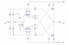
I have heard this power amplifier. Also with currently models very hard to beat after replace old capacitors through new devices.I have on hand a pair of German amplifiers that are using power diamond buffers as outputs.
In the attachment the complete schematic and some informations to Fujitsu's MET's for power stages.
Attachments
Last edited:
I can access geocities site .Please post up some photos!
Geocities is gone now!
I have heard this power amplifier. Also with currently models very hard to beat after replace old capacitors through new devices.
In the attachment the complete schematic and some informations to Fujitsu's MET's for power stages.
Thanks Tiefbas.
Yes they are nice amps. Feedbackless power stage.
I suppose the outputs devices to be hardly matched.
I have drawn the front end schematic another way.
Attachments
- Status
- This old topic is closed. If you want to reopen this topic, contact a moderator using the "Report Post" button.
- Home
- Amplifiers
- Solid State
- four transistor emitter follower (diamond buffer) as power output stage?