you are right, arround the TL071 there is something wrong. I have clone this topology some years ago, but without offset servo (I use floating GND). Therefore I have overlooked all sketched errors arround this servo unit.Hi tiefbassuebertr,
There seems to be something wrong in the ES200 schematic. The DC-Servo looks strange. The poor TL071 has its output connected straight to the amp output.
Not exactly, this Circuit is intended for a 32 ohm headphone Load and so outputs above 2 volts are not normally required on a Continuous basis, this we can lightly Bias because we are only biasing what the load requires with no overkill. However, the dyno bias circuit I described is upon THIS PDF. http://www.diyaudio.com/forums/attachments/solid-state/65884d1150415890-four-transistor-emitter-follower-diamond-buffer-power-output-stage-dyno-bias-ii-schematic.pdfThe circuit in this diagram switches from class-A to class-AB at a few volts of output, is that deliberately?
jd
The link to the PPA Buffer is another Design altogether. The PPA headphone amp (Phil’s portable Amplifier) was a DIY Community project I did years ago. I note that Tangent has redesigned the buffer for that Amp. Oh I have no Idea who or how THIS schematic http://www.diyaudio.com/forums/attachment.php?postid=594841&stamp=1110543824 As it is not of My mind. The schematic to the PPA Headphone Amp is HEAR.
Last edited:
Those with access to a good library should see the October 1976 Wireless World page
74.
The schematic is in the Circuit Ideas section. It had a single transistor running class A for voltage gain as a front end and had no feedback. The output stage is essentially the Cool Follower 99 design.
74.
The schematic is in the Circuit Ideas section. It had a single transistor running class A for voltage gain as a front end and had no feedback. The output stage is essentially the Cool Follower 99 design.
you are right, arround the TL071 there is something wrong. I have clone this topology some years ago, but without offset servo (I use floating GND). Therefore I have overlooked all sketched errors arround this servo unit.
Could you post your circuit?
Is is still your favourite OPS?
No. Unfortunately I haven't the final "real life" circuit and the images of a wide range of "real live" THD/IM measurements so as square wave behavior available (delete for a long time).Could you post your circuit?
Is is still your favourite OPS?
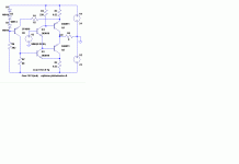
But I recall, the results are very good. However I had prefer in those days the results from a two MOSFET circlotron power buffer topology, especially by the audible sonic check. From the simulation aera I have found two preliminary schematics based of Audiolabor ES-200 without commonly used voltage gain stages - I recall to a hard work for approximate the NTC's for stable idle current in those days
Attachments
Last edited:
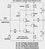
Another way to abuse four transistors...
And probably much lower supporting parts count.
As you won't be needing any CCS nor bootstraps.
Easily gets within 2V of either rail.
Unless someone else shows prior art, I'm taking the
liberty of naming it after myself! I think this circuit
might actually prove to be important some day.
And probably much lower supporting parts count.
As you won't be needing any CCS nor bootstraps.
Easily gets within 2V of either rail.
Unless someone else shows prior art, I'm taking the
liberty of naming it after myself! I think this circuit
might actually prove to be important some day.
Attachments
Last edited:
Uh, nevermind... I've just run this sim with power supply noise added.
Probably the worst PSRR ever! Which is sad, cause this circuit really
seemed to do amazing things with very few parts. Now I see the cost
will be in getting power clean enough.
The problem lies in paraphase. The "error" to be corrected by applying
a counter-modulated current is computed against the rails. If those rail
reference points move? Its a total disaster. I need to rethink this wheel.
Member
Joined 2009
Paid Member
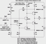
Ken's circuit fixed
Here is a way round the problem.
Maybe not very elegant, as it requires one more transistor, but it does the job:
Uh, nevermind... I've just run this sim with power supply noise added.
Probably the worst PSRR ever! Which is sad, cause this circuit really
seemed to do amazing things with very few parts. Now I see the cost
will be in getting power clean enough.
The problem lies in paraphase. The "error" to be corrected by applying
a counter-modulated current is computed against the rails. If those rail
reference points move? Its a total disaster. I need to rethink this wheel.
Here is a way round the problem.
Maybe not very elegant, as it requires one more transistor, but it does the job:
Attachments
Nevermind... You already had three diodes in the bias string.
Somehow I miscounted when I copied over the changes...
I don't think a big transistor and current necessary here.
Q2's base only demands about 120uA<Ib<400uA.
2N5401 with 330 and 390 in the splitter work equally well.
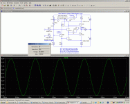
With:
2VPP ripple at 120Hz added to the the top supply,
2VPP ripple at 400Hz added to the lower supply.
2VPP input at 1KHz.
I see both ripples out -60db down from the signal.
Cascoding can win you another -3db, if it matters.
Last edited:
Your PSRR fix works! I'm tempted to try that with a real WCF.
I especially like the direct capless coupling.
There is one issue left that might need resolved? 0.2V offset.
Q1 is not a good voltage compliment to Q4 at these currents.
If its gonna be the output stage of some other voltage stage
with global feedback and/or servo, this nitpick may not matter.
But I think we would want feedback loops kept short, and not
wrap the output stage into GNF. So the offset needs to go...
A resistor added to the base or emitter of Q4 fixes the offset,
but adds distortion by loosening the grip of local error correction.
This might be fixable by selecting different transistors, outside
the LTSpice default set...
Attachments
Last edited:
I posted this at Swedish HiFiForum.nu a year ago. Seems to be some resemblance . Got the idea from JLH Class-A with the driver PNP instead of NPN. Think one should add a servo though to take care of initial offset and tempdrift. The CCS should also be made up of BJTs.
At work now. Will post my later version with symmetrical JFET/MOSFET driver stage when I get home.
An externally hosted image should be here but it was not working when we last tested it.
At work now. Will post my later version with symmetrical JFET/MOSFET driver stage when I get home.
Offset correction
Here is a fix, after all, but it requires two more transistors:
Q7 senses the Vbe of Q4; the delta Vbe between Q1 and Q4 in fact, since Q1 and Q7 are identical (matched).
It then corrects the additional bias current provided by Q6.
For the scheme to work, the Vbe of Q4 under initial bias conditions must be larger than the Vbe of Q1; this is why I changed Q3, 4 to TIP2955.
R8 accounts for the different currents in Q1 and Q7, as it wouldn't be practical to operate them at the same current.
The correction is rather loose, more a stabilization than a regulation, and initial values have to be in the right range for things to work properly.
There is still plenty of room for improvements/refinements, as the THD is 33ppm, pure 2nd harmonic.
Attachments
Can not see any better offset characteristics than the simplistic one at the right. Cirka 180mV on both. Adding the servo (and in this case a cap) can be a possible fix.
Neither a quick temp-check seem to be better than the left. But it seems good enough anyway.
The right one indicates lower distortion but the left one has the better overtone spectrum with 2nd dominating.
Neither a quick temp-check seem to be better than the left. But it seems good enough anyway.
The right one indicates lower distortion but the left one has the better overtone spectrum with 2nd dominating.
Attachments
Can not see any better offset characteristics than the simplistic one at the right. Cirka 180mV on both. Adding the servo (and in this case a cap) can be a possible fix.
Neither a quick temp-check seem to be better than the left. But it seems good enough anyway.
The right one indicates lower distortion but the left one has the better overtone spectrum with 2nd dominating.
The offset correction circuit is disabled when Vbe(PNP)<Vbe(NPN), which is the case for the 45H11 / 2N3019 couple.
- Status
- This old topic is closed. If you want to reopen this topic, contact a moderator using the "Report Post" button.
- Home
- Amplifiers
- Solid State
- four transistor emitter follower (diamond buffer) as power output stage?


