M2 is still my fave ..... one to stay
it has Iron for gain , not fluffy 3 legged fuses

")
Most excellent. In what appears appears to be your copious free time, you
might want to take a look at the inverting amplifier case as well, as I found
it the simplest.
I have completed analysis of the 6 the combinations of Rload/Rsense resistor placement w.r.t. each other and ground. LTSpice simulations appear to verify the correctness of the equations shown.
Attachments
I have completed analysis of the 6 the combinations of Rload/Rsense resistor placement w.r.t. each other and ground. LTSpice simulations appear to verify the correctness of the equations shown.
Wow lhquam. As the like saying goes, when it rains great science from you, it pours.
The priceless infinite damping factor of your diyF7 prototypes maybe preserved by having the two overall feedback loops originate at the terminal
M2 is still my fave ..... one to stay
it has Iron for gain , not fluffy 3 legged fuses
Funny you should bemoan .."Fluffy 3 legged Fuses "....you have produced fantastic Babelfishes.....with them
But on the other hand ...i just happen to have a few of the prescribed transformres for M2....
and when reading between the lines...and on the lines for that matter, Papa's enthusiasm for F7 is quite obvious .....i believe he enjoyed making this one more than any other for some time....
Last edited:
After some study of the ALF08N16V and ALF08P16V datasheets, it looks like the rail voltages could be increased to 32V and the bias current to around 2A, giving an amplifier that could easily produce 40W output. Of course the input JFETs would need to be cascoded to keep them within their operation limits, and the heatsinks would need to be larger or fan cooled. Obviously this would not fit within the FirstWatt parameters, but would be a DIYer's delight!
After some study of the ALF08N16V and ALF08P16V datasheets, it looks like the rail voltages could be increased to 32V and the bias current to around 2A, giving an amplifier that could easily produce 40W output. Of course the input JFETs would need to be cascoded to keep them within their operation limits, and the heatsinks would need to be larger or fan cooled. Obviously this would not fit within the FirstWatt parameters, but would be a DIYer's delight!
Probably best to get the T03 devices if you intend to push them to 64W each.
Or get the double die 16N16W and 16P16W if you don't like metal cans
Quite a few pages added to F7 review if no one noticed.
Fascinating review. I got lost in the description of the technical aspects by Nelson fairly early but enjoyed reading it. I thought the review by Dawid was excellent and more understandable than other reviews on Firstwatt products by 6Moons. The F7 appears to be another winner by Nelson but I was expecting this. If it were not so he would not have released it.
. . . I always assume that 6moons will photograph the interior. That's why I hide anything I don't want you to see.
No joke my dear generg, you are definitely to blame now that Srajan show the bottom side of the F7 on 6moons audioreviews: FirstWatt F7, page 5.In the case of the F7 it seems to be the bottom side of the amp.....
Joking!
Probably best to get the T03 devices if you intend to push them to 64W each.
Or get the double die 16N16W and 16P16W if you don't like metal cans
No TO3 devices.
I would like to use the DIYAudio Universal Mounting Spec board and heatsink layout that is used for F4, F5, F6, ... boards. I was thinking about using pairs of the TO-247 (ALF08N16V and ALF08P16V) FETs. Can one safely parallel laterals without source resistors by matching for Vgs and gm at the idle current?
Alternatively, using the TO-264 packages, I guess I could place the FET pads further back into the board by about 0.18" so that the leads of the TO-264 package are in a suitable position in relation to the thru holes.
Yes you can certainly parallel devices if you already have 8N16V and 8P16V.
Here is my amp with paralleled output devices.
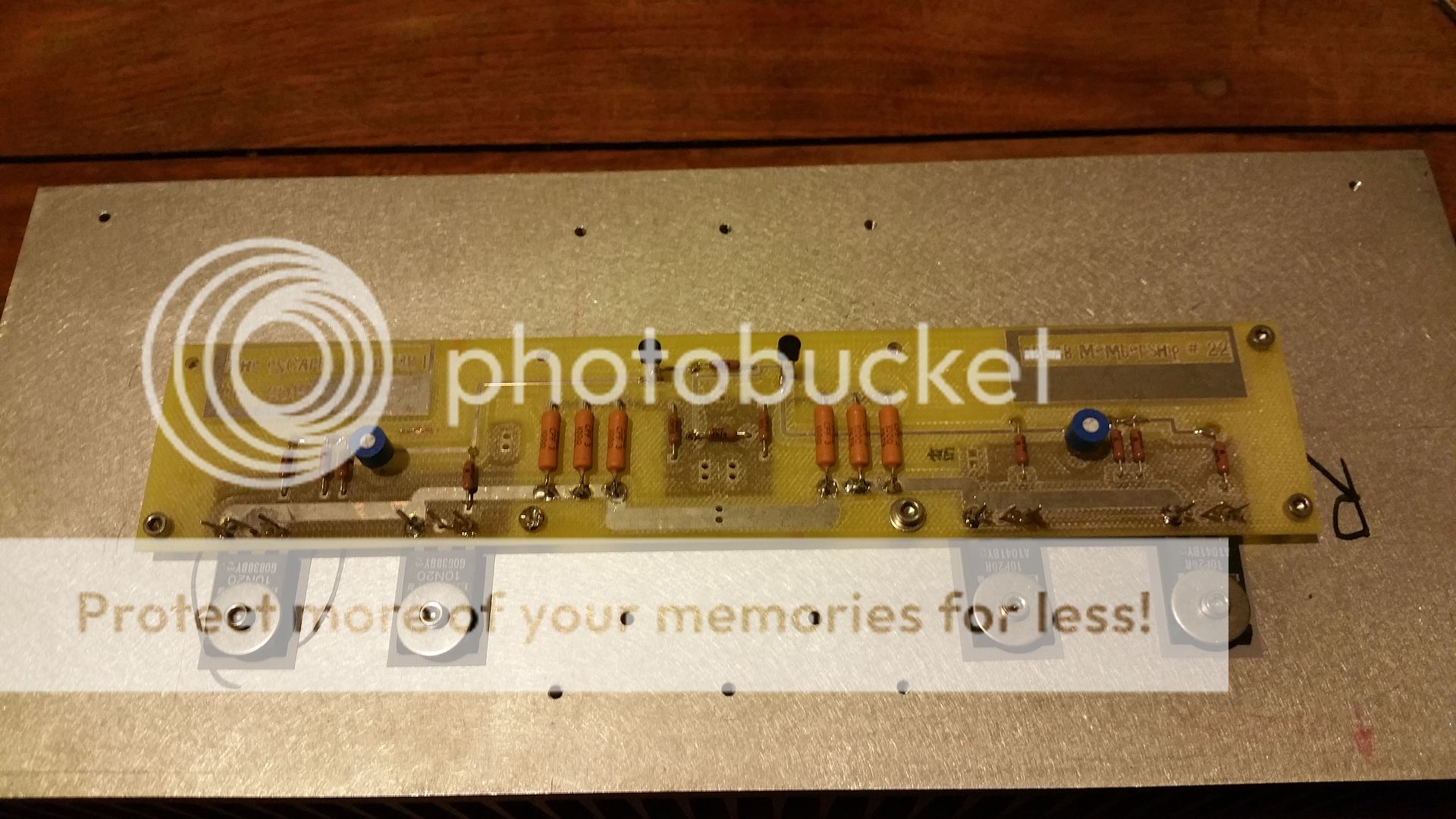
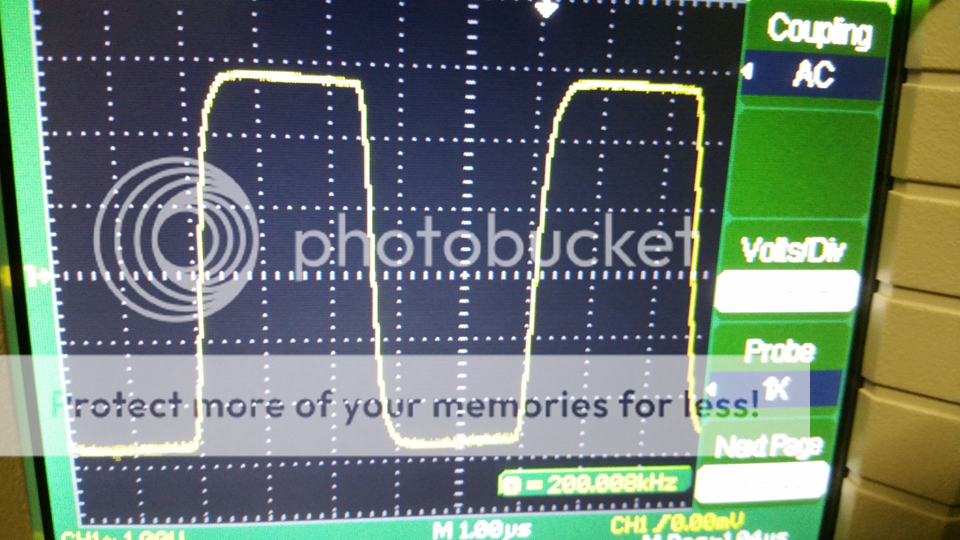
Here is 200 kHz square wave.
Yes you can certainly parallel devices if you already have 8N16V and 8P16V.
Here is my amp with paralleled output devices
...
Yes, that is what I had in mind. Did you parallel the devices for higher gm or to handle higher power dissipation?
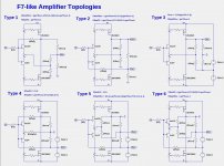
Looking at your board layout: Did you use the topology that I show as Type 1 in post #441? Without cascoding the JFETs, how high did you go with the rail voltages?
Last edited:
Yes, that is what I had in mind. Did you parallel the devices for higher gm or to handle higher power dissipation?
Looking at your board layout: Did you use the topology that I show as Type 1 in post #441? Without cascoding the JFETs, how high did you go with the rail voltages?
I built this before F7 circuit was known. This is a simplified F5 built to to meet my goals (simplification), no source resistors, no current limiting circuitry, no biasing thermistors, as simple as possible.
Mine is biased at 2A.
I paralleled to get the damping figure of about 50 and to achieve the bias of 2A.
Rails are between 24 and 25 Volts.
Last edited:
I built this before F7 circuit was known. This is a simplified F5 built to to meet my goals (simplification), no source resistors, no current limiting circuitry, no biasing thermistors, as simple as possible.
Mine is biased at 2A.
I paralleled to get the damping figure of about 50 and to achieve the bias of 2A.
Rails are between 24 and 25 Volts.
Thank you. That explains everything.
Thank you. That explains everything.
30V and no cascode should be fine in this circuit with 7mA Jfets.
I've done that before without issues.
[Review] First watt F7 amplifier at 6moons, with measures
[Review] First watt F7 amplifier
-> 6moons audioreviews: FirstWatt F7
[Review] First watt F7 amplifier
-> 6moons audioreviews: FirstWatt F7


- Home
- Amplifiers
- Pass Labs
- First Watt F7 review