Another little snippet on the review that is still going at 6Moons.
A week or so later, Dawid checked in. "This is a seriously *******' good amplifier, Srajan. I don't think you will get anything valuable and new from my impressions yet after several days and a 'triangulation, decomposition and reconstruction' phase, I finally had to tell someone. I am utterly amazed by what Nelson did here. With my Boenicke W5, it's a jaw-dropping experience. I'm not hugely familiar with tube amps but at least now to some small degree, I understand why you switched. For me it's a mind-opening experience. It's good to finally witness what you wrote about for so many years. Yet what strikes me the most is that in the F7's case, it's not merely about blunt warmth and fuzziness that often come with it. To my ears this amp has huge doses of smoothness, delicacy, saturation and charm yet still is able to maintain an exceptionally informative character and wide bandwidth. Very refined and polished, it's a spectacular pleasure machine. But I'm guessing all these aspects are Nelson's standard features." Our FirstWatt rookie definitely had his nookie and was deep in the afterglow of it. Once he returned to his senses, I was mighty curious just how he would break down his experience into audiophile jargon. After all, "seriously *******' good" is what we all want from and for our components yet from a review—sniff—we expect a lot more.
... more in due time...
The circuit in post #397 is totally bogus. But here is an abstract version that appears to work. This circuit has an inverted output and infinite damping factor.
From the Y equation , R1[input Z] =10K [spec], and RfbN =47 K for a gain of -4.7 [close to spec]. These two R values are then plugged in the Rfbp equation to give:
Rfbp = 8.25 {Gm x Rsens -1}. Rsens is/has to be small in value; say 0.5 Ohms, and make Gm = 5 A/V. So, Rfbp = 8.25 x 1.5 = 12.4 K
The value of Gm needs to be known with certainty. If not, then start with a high valued Rfbp using standard resistors; say 47 K, and decrease its value to 39K, 33K, 27K, 22K, 18K 15K, 12K 10K...until the amp oscillates if this design allows it.
And here is a circuit that simulates fairly well for the abstract circuit of post #401.
Is the suspected PSU in F7 two floatings ones for L and R channels? In the equation to determine the value of Rfbp, set the value of Rfbp to an arbitrary 1000K [1 Meg]; meaning a trivial extent of positive feedback; meaning it defaults to a phase- inverting diyF5. The resultant value of Gm x Rsense ~ 122. If Gm has an actual value of 5 A/V, then Rsense = 24 Ohms. Since Rsens = 0.5 Ohms [can't change it], then Gm = 244 A/V.
The circuit in post #397 is totally bogus. But here is an abstract version that appears to work. This circuit has an inverted output and infinite damping factor.
Damping factor is defined as the impedance of the load divided by the internal impedance of the power amp driving it. A damping factor which has an infinite value requires the internal impedance of the power amp be equal to zero; which is appears to be a principal objective for diyF7.
Going back to Post#365, plug in the two given equations zero Ohms for Rint. Granted OLG and CLG are exactly known, then the unique value of RFbp is calculated which satifies Rint = amp's output impedance = zero.
And finally, I think I have the circuit Nelson eluded to in post #392, which has fewer resistors yet.
Interesting circuit. The power output Mosfets operate in the common drain [grounded] configuration. This means that the phase inverted power output voltage emanates from the naturally low impedance of the Mosfets' opposed sources. The open loop voltage gain of this amp is solely from the complementary JFETs; because the voltage gain of the Mosfets is 1
The node at the joined JFET's gates is a virtual ground or a summing junction of two out of phase AC signals. Except there is an AC feedback voltage [from OUT+] to the joined sources of the JFETs. The JFETs now do additional/independent amplification operating in the common gate configuration; essentially generating the closed loop gain which is lower in value than open loop voltage gain.
Interesting circuit. The power output Mosfets operate in the common drain [grounded] configuration. ...
Actually the output FETs are running common source with the power supplies floating. If you look closely the gate-to-source voltages (Vgs) are defined by the currents thru P1 and 2, whose wipers connect to the gates and another terminal connects to the source.
Actually the output FETs are running common source with the power supplies floating. If you look closely the gate-to-source voltages (Vgs) are defined by the currents thru P1 and 2, whose wipers connect to the gates and another terminal connects to the source.
Thanks lhquam.

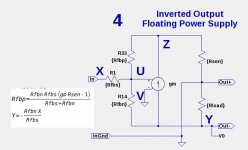
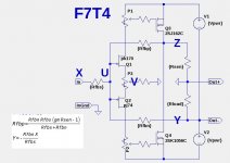
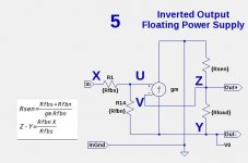
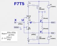
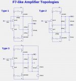
I have done more analysis and simulation of the feedback topologies for amplifiers of the F7 variants, such as shown below. Here is a summary of my findings:
Type 1: Simulates fairly well, but might be too sensitive to resistor values.
Pro: Negative speaker terminal is grounded
Con: Sense resistor must be .5-1.0 Ohms
Kfbn negative feedback resistor must be relatively small
Type 2: Simulates well.
Pro: Good resistor values and performance with small Rsen values
Con: Negative speaker terminal is active
Type 3: Simulates well.
Pro: Simple parameter relationships
Low value sense resistor
Negative speaker terminal is grounded
Con: Floating power supplies - probably disqualifies this choice
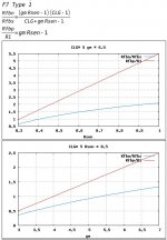
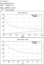
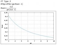
The equations and plots below are for the resistor values with an infinite damping factor. The Type 3 topology is unique in that the Sense resistor Rsen is determined from gm and CLG alone.
Type 1: Simulates fairly well, but might be too sensitive to resistor values.
Pro: Negative speaker terminal is grounded
Con: Sense resistor must be .5-1.0 Ohms
Kfbn negative feedback resistor must be relatively small
Type 2: Simulates well.
Pro: Good resistor values and performance with small Rsen values
Con: Negative speaker terminal is active
Type 3: Simulates well.
Pro: Simple parameter relationships
Low value sense resistor
Negative speaker terminal is grounded
Con: Floating power supplies - probably disqualifies this choice
The equations and plots below are for the resistor values with an infinite damping factor. The Type 3 topology is unique in that the Sense resistor Rsen is determined from gm and CLG alone.
Attachments
While you guys smarter than me are trying to figure out the circuit...
I remember when Nelson's first words about the F7 came out he said something like "this isn't an amplifier for everybody". I assumed at the time it would be an amplifier for hi-Z loads and efficient speakers.
Now reading the 6moons stuff it looks like this is an amp capable of driving low-Z load in an unusual way. Wattage aside, why is Nelson putting out the "not for everyone" disclaimer? Any guesses?
While you guys smarter than me are trying to figure out the circuit...
I remember when Nelson's first words about the F7 came out he said something like "this isn't an amplifier for everybody". I assumed at the time it would be an amplifier for hi-Z loads and efficient speakers.
Now reading the 6moons stuff it looks like this is an amp capable of driving low-Z load in an unusual way. Wattage aside, why is Nelson putting out the "not for everyone" disclaimer? Any guesses?
The same thing applies to every Firstwatt amp.
Not everyone likes chocolate either.
The same thing applies to every Firstwatt amp.
Not everyone likes chocolate either.
NP did say that his goal was to emulate "the beast".
I simply wait for the review Srajan gives.
Of course the way the amp is introduced in so many parts and even reflecting the contributions of this thread is a bit new and increases curiosity.
I am mostly interested if Srajan and his comrades see the effect of theositive feedback and if this effect is very dependent of Speaker load type.
So,that F7 might be magic with this speaker and more normal with the other.
I hope that the review will give Nelson many sold amps.....!
I simply wait for the review Srajan gives.
Of course the way the amp is introduced in so many parts and even reflecting the contributions of this thread is a bit new and increases curiosity.
I am mostly interested if Srajan and his comrades see the effect of theositive feedback and if this effect is very dependent of Speaker load type.
So,that F7 might be magic with this speaker and more normal with the other.
I hope that the review will give Nelson many sold amps.....!
Yes...the positive feedback effect varying with load seems to be the big thing here. The speakers they are reporting using the F7 with are monitors with sensitivities in the mid 80's and pretty reactive low-Z loads. Not your typical first watt-ish speakers. I feel like 6moons is setting us up for some kind of reveal about the circuit and its use with either low-Z speakers or speakers with highly variable loads.
I have done more analysis and simulation of the feedback topologies for amplifiers of the F7 variants, such as shown below. Here is a summary of my findings:
Type 1: Simulates fairly well, but might be too sensitive to resistor values.
Pro: Negative speaker terminal is grounded
Con: Sense resistor must be .5-1.0 Ohms
Kfbn negative feedback resistor must be relatively small
Type 2: Simulates well.
Pro: Good resistor values and performance with small Rsen values
Con: Negative speaker terminal is active
Type 3: Simulates well.
Pro: Simple parameter relationships
Low value sense resistor
Negative speaker terminal is grounded
Con: Floating power supplies - probably disqualifies this choice
The equations and plots below are for the resistor values with an infinite damping factor. The Type 3 topology is unique in that the Sense resistor Rsen is determined from gm and CLG alone.
Nice work lhquam - my vote goes to typpe 2
I have done more analysis and simulation of the feedback topologies for amplifiers of the F7 variants, such as shown below. Here is a summary of my findings:
Type 1: Simulates fairly well, but might be too sensitive to resistor values.
Pro: Negative speaker terminal is grounded
Con: Sense resistor must be .5-1.0 Ohms
Kfbn negative feedback resistor must be relatively small
Type 2: Simulates well.
Pro: Good resistor values and performance with small Rsen values
Con: Negative speaker terminal is active
Type 3: Simulates well.
Pro: Simple parameter relationships
Low value sense resistor
Negative speaker terminal is grounded
Con: Floating power supplies - probably disqualifies this choice
The equations and plots below are for the resistor values with an infinite damping factor. The Type 3 topology is unique in that the Sense resistor Rsen is determined from gm and CLG alone.
Thanks lhquam for this concise summary of your valuable knowledge which you generously granted DIYers.
- Home
- Amplifiers
- Pass Labs
- First Watt F7 review