You cannot handle 48V with the JFETs. The original F5 had about 35W per output FET. How about 25V rails and 1.4A bias?
of course I added the +-24V to 48V and with 1.2-1.4A bias the F7 is in the ballpark of F5 and all the others concerning power for one Mosfet.
As you wrote......

so PR I see no danger.....!
F7.pdf?
See Attachment
Attachments
of course I added the +-24V to 48V and with 1.2-1.4A bias the F7 is in the ballpark of F5 and all the others concerning power for one Mosfet.
As you wrote......
so PR I see no danger.....!
I knew exactly what you meant.
All lateral mosfets have that arrangement (dumb bastards). hahahaha
yes I forgot..... my world is too much IRF oriented.
heavyDump generg
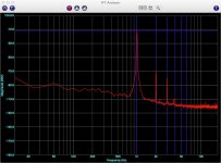
That looks just pretty good: somewhere around 0.1% THD with H2/H3=10dB. I assume that spectrum is for 1W into 8R at 1kHz.adjusting k2......
Last edited:
All lateral mosfets have that arrangement (dumb bastards). hahahaha
ya picodumb^2

what's with T03 ?
ya picodumb^2
what's with T03 ?
Ok smart ****. Hahahaha
Are you sure you are not my older brother. Always razzin poor pico
hahahahaha
yes I forgot..... my world is too much IRF oriented.
heavyDump generg
Hey Generg, My world was too, until Infineon bought them and they laid me off... I'm back working again but IR is no More! (since the first of 2015 Actually). From what I know, Buying Vishay parts is your best bet if you want IRF240/610 types. That would be all the parts from 2005 on I believe
IR did have an GaNi part that is promising, like a SIT, but, knowing what goes on there it aint worth chasing. There is a model of LG Surround system that actually has an IR GaNi part and a Vacuum state part in it??? Interesting...

I have figured out the equations for the 3 circuit topologies shown in post #269 http://www.diyaudio.com/forums/pass-labs/275921-first-watt-f7-review-27.html#post4565114. In all cases the solution is that which makes the output insensitive to the load resistance, i.e. infinite damping factor. These equations are simple enough that the topologies can be compared.
Attachments
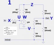
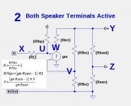
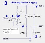
I have figured out the equations for the 3 circuit topologies shown in post #269 http://www.diyaudio.com/forums/pass-labs/275921-first-watt-f7-review-27.html#post4565114. In all cases the solution is that which makes the output insensitive to the load resistance, i.e. infinite damping factor. These equations are simple enough that the topologies can be compared.
Most excellent. In what appears appears to be your copious free time, you
might want to take a look at the inverting amplifier case as well, as I found
it the simplest.
you might want to take a look at the inverting amplifier case as well, as I found
it the simplest.
Me too. Hehehehehe
Last edited:
Ok smart ****. Hahahaha
Are you sure you are not my older brother. Always razzin poor pico
hahahahaha
That was A.R.S.E (nothing worse)
I'll use smarty pants in the future to avoid possible misinterpretation of censoring. hahahahaha
Most excellent. In what appears appears to be your copious free time, you
might want to take a look at the inverting amplifier case as well, as I found
it the simplest.
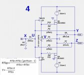
Something like this?
Attachments
I have figured out the equations for the 3 circuit topologies shown in post #269 http://www.diyaudio.com/forums/pass-labs/275921-first-watt-f7-review-27.html#post4565114. In all cases the solution is that which makes the output insensitive to the load resistance, i.e. infinite damping factor. These equations are simple enough that the topologies can be compared.
Can you please explain what Rint and R1 actually are ie: what values they are.
Can you please explain what Rint and R1 actually are ie: what values they are.
Rint is the internal resistance of amplifier, and gm is is its transconductance. In my earlier posts I was incorrectly using a voltage=>voltage amplifier model, where Rint is necessary parameter to characterize its behavior. With the correct Voltage => current model, gm incorporates the output MOSFET transconductance and internal resistance model into a single gm parameter.
R1 is an free parameter in the design for use both as a gate-stopper to the JFETs and to tune the -3dB rolloff of the amplifier.
- Home
- Amplifiers
- Pass Labs
- First Watt F7 review