I got most of my parts in... I've put together the regulator, and it works fine.
I'm just wondering where that .47uf bypass cap goes? I've got a 4uf/16v black gate for E5.
I've removed caps 3 & 4 from the bottom of the board (under the heatsink), but left alone the caps @ 2.
Thanks,
JG
I'm just wondering where that .47uf bypass cap goes? I've got a 4uf/16v black gate for E5.
I've removed caps 3 & 4 from the bottom of the board (under the heatsink), but left alone the caps @ 2.
Thanks,
JG
In contrast to the extent of the improvements you have found with this mod, Peter's remarks were less categorical and he suggested it was a matter of taste.
I ask myself if at least some of the improvements you experienced could be coming from the fact that you took some critical components off the main board.
I have not seen your assembly which may be as well made as Peter's, but I am definitely going to redo the mechanics of mine before contemplating any other mods.
Tony - as always with this hobby, results are very subjective and every one of us will no doubt form a different opinion about this mod or that mod. For the record though - most of the caps on my board are standard apart from the few that Peter suggested as part of his minimal build. What I have done is supplied the 5V from a seperate power supply and disconnect the DAC from this supply (because i don't use it). Certainly my Shiga is not full of changes from the original at all - what changes I have made in the past have resulted in much smaller increases in sound quality than the fitment of this re-clocking circuit - IMO
")
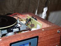
As for the mechanics - I can assure you that mine is much like yours sounds - ie. somewhat rough and ready!! - it is just sat on those M8 bolts you see in the pics and the whole thing is still sat on an old piece of plywood i found in the garage! I also have a little trouble getting it exactly level but figured it can't be that important! and i reckon that 2 diagonal supports might be stressing the top plate a little when tightened up - really, a mechanical masterpiece it ain't!!
I do feel however that this little circuit that Peter spotted is worth an hour or two of everybodies time to check out - there are no esoteric parts to be found and bought - the 2 chips and a 1Meg resistor will cost less than £1 - and you might just get on with it like I have.
FWIW - I am now 2 albums in, listening to my Shiga with this re-clocker using the original resonator - and I think it is pretty damn good - I'm not used to listening with headphones too much but the music is rich and full of texture still - yep i like.
Does anyone have an extra clamp?
My player didn't come with a magnetic clamp. The plastic clamp itself doesn't work too well. I would be happy to buy an original clamp with magnet in case someone has one to spare.
Please, send me a private message if you would like to help me out.
I still haven't found a new clamp. The player is useless without it.
Any ideas??Are there alternatives to the 74ACT14 and 74AS74?
Could I use 74HCT14 and 74HC74?
I think both those alternatives could be used - provided you have a hex invertor and a d-type flip-flop (which these are) and they can be used at the frequencies involved (which i think they can) ............................ then they SHOULD work. I'm not 100% sure about the intricate differences between the chips in these series but if you have them to hand I would give 'em a go.
I think Peter initially used 74act14 & 74as74 because they were the ones used in the original schematic from the CEC - he did say that some experimentation with different chips might be good - these things are cheap so it shouldn't be too much of a problem if these particular alternatives don't work.
I still haven't found a new clamp. The player is useless without it.
I have 2/3 of an original jvc one going spare - it has the lower, larger plastic disc and the magnet part - it's just missing the small, upper disc - workes fine though.
if you get no joy from elsewhere feel free to pm me - it's yours if you need it.
gI'm looking forward to hearing what you think about it.
and eventually I got it working! I'm just started to listen some well known tracks to understand if there's some improvement. Loudspeakers deliver music and this is a good thing due to the mistakes I made in this process. Thank you for your help, it was a decisive factor (and thanks to Peter obviously). However, first impression is very good, not worse for sure.
Attachments
Last edited:
OK, found the info. "data" comes from the pad closest to the chip on the JVC board, and MCK goes to the pad furthest from the chip. Centre pad is ground.
Local decoupling: I just add a decent sized cap on the +5V feeds ok?
Last, there may be another reason for why herewegoagain's JVC showed such an improvement: he is using just the 300/100R resistor setup whereas Peter is using the transformer.
mmmm.
Fran
Local decoupling: I just add a decent sized cap on the +5V feeds ok?
Last, there may be another reason for why herewegoagain's JVC showed such an improvement: he is using just the 300/100R resistor setup whereas Peter is using the transformer.
mmmm.
Fran
Fran, take a look at herewegoagain post #3878 and other recent posts from him, they're very helpful.
Remove the crystal on jvc board,
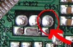
connect MCK-ex from Peter scheme to the pad from LC78601 pin61 (see picture)
connect board dout to 74AS74 pin12
I fed the circuit with +5V from the jvc board, the pad between dout and gnd
I omitted pulse transformers, 0.1uF cap and 300R, taking the signal directly from 74AS74 pin 9.
Remove the crystal on jvc board,
connect MCK-ex from Peter scheme to the pad from LC78601 pin61 (see picture)
connect board dout to 74AS74 pin12
I fed the circuit with +5V from the jvc board, the pad between dout and gnd
I omitted pulse transformers, 0.1uF cap and 300R, taking the signal directly from 74AS74 pin 9.
Attachments
Thanks Massimo:
MCK goes to red circled pad, data goes to the pad nearest the chip and the centre pad is ground (which I won't be using because I'll use the gnd from the power connections on the JVC board).
Then not use the 300/100 on the JVC board, but rather from pin 9 from 74AS 74.
OK, I think I have it!!!
Lots of activity on this thread!!!
Fran
Thanks Massimo:
...............data goes to the pad nearest the chip................
Fran
Fran - no.... the 'data' comes from the 'Dout' pad on the side of the jvc board - the place where you would normally put your 300/100 resistors.
this circuit 're-clocks' that output data using the clock/crystal/resonator -
data goes to the pad nearest the chip
data goes to AS74AS pin12
I've sent some pictures to your mail
easy re-clocking
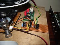
OK I've attached the pic of the circuit I built on vero to illustrate where things go.
the board has 2 chips and 2 caps for local decoupling - if you are using a crystal or resonator then you'll have that and a 1meg resistor too.
the LH chip is the 74act14 the RH one is the 74as74 - they are both orientated the same way with each pin 1 closest to the camera on the right.
The twisted black and yellow wires are +5v and ground - you can attach them to the pads next to the Dout pad on the side of the board. Both chips, pin 7 is ground and pin 14 is +5v.
The single black wire comes from that Dout pad and connects to pin 12 of the 74as74 (data in).
The single orange wire is connected to pin 6 of the 74act14 - it is the clock going off to the board - you can see it disappear underneath where it connects to the old resonator pads (circled in the pic above - the furthest one from the chip)
The single grey wire is connected to pin 1 of the 74act14 - it is the clock input from my Flea/Tent - if you are using a crystal/resonator then you'll have it, and a parallel 1Meg res across pins 1 & 2 of this chip.
The twisted yellow & green wires are my 'data out' - the yellow is connected to pin 9 of the 74as74 (just hidden from view in the pic) - the green is ground. These 2 wires go to my RCA output socket via the 300/100R divider.
for decoupling I'm using a 100u ZA and 100n MKT but for my quick lash up on breadboard i just used what was at hand. The +5v is the same as is used by the board so some experimentation might be in order to suss out the effect of these caps on the sound.
hope this helps fellas
Attachments
Last edited:
Last, there may be another reason for why herewegoagain's JVC showed such an improvement: he is using just the 300/100R resistor setup whereas Peter is using the transformer.
mmmm.
Fran
I think if I had a suitable transformer then I probably would have used it just to keep faithful to the original schematic from the CEC. But I have never used an s/pdif traffo and don't have one available - so i just reckoned that the usual 300/100R divider would do the job. Actually I'm not even sure that these 300/100 values are still valid, now that the Dout has effectively been buffered by the D-type! - it sounds good though so I'm not too concerned by it.
I've been listening to my Shiga all morning now using the original resonator to re-clock and have just removed it and re-connected the Flea/Tent. There is certainly an improvement in clarity now and the presentation just seems more 'right'!
- bass goes a little lower and highs are crisper - it sounds almost 'live'. - BUT, the difference between this and using the resonator is smaller than i would have thought - in fact had I built this re-clocker and used the resonator (or perhaps the HE crystal I have) BEFORE building the Flea then I might have not bothered with it at all. This circuit really does seem to 'get everything in order' before it leaves the player - which IME translates into music that is - dare I say it? - more ordered(!), more tangible and more realistic. Or am I talking twoddle?
de-coupling
err yep - across +5v and ground - and as close to the pair as is practical
Very usefil, many thanks.
The caps are on the 5v supply right?
Fran
err yep - across +5v and ground - and as close to the pair as is practical
- Home
- Source & Line
- Digital Source
- Finally, an affordable CD Transport: the Shigaclone story