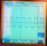
Yeah i guess the DAC end would be more useful- those traces were just posted in response to massimo so he could compare them with his reclocking ones.
In reality I'm not sure that the exact shape of the trace has much bearing on sound quality - within reason obviously !!
In reality I'm not sure that the exact shape of the trace has much bearing on sound quality - within reason obviously !!
those traces were just posted in response to massimo so he could compare them with his reclocking ones.
Thank you. I'll redo the circuit from scratch.
One thing i did notice Peter - if I take the MCLK back to the main board after 3 invertors (pin 6) then I still get the occasional skip and distortion - but if I just use 2 invertors (pin 4) or 1 invertor (pin 2) then it will work just fine - I've listened to it now using either 1 or 2 invertors for several hours and it's stable. Any ideas why this might be happening? Why did you suggest 3 invertors on the original cct? - was it a timing issue ? - sorry for all the questions - I'm hoping to learn something here!")
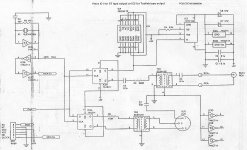
I just copied (exactly) the circuit from CEC TL0, see below. In such moded Shigaclone there is no skipping at all. Also, attched is the output from CEC TL0 (terminated with 75R).
Attachments
Isn't there a thread around here somewhere that compared various transformers (pulse vs newava mainly)? IIRC, the neava one had a considerably cleaner square wave with less ringing than the pulse one.
Fran
After a very quick look here is one thread discussing the newava.
http://www.diyaudio.com/forums/digital-line-level/139222-pulse-transformers-spdif-aes-ebu-2.html
In fact, the Newava transformer mentioned in this thread is the very one Peter recommends in his 'Transport' thread.
Regards,
Dan
Last edited:
I'm not familiar with Newawa and I only mentioned it because someone else earlier recommended it; I will get one with my next DK order though. The SC transformer I'm using presently is at least 15 years old and I recall that it sounded not too bad. OTOH, I also tried this SC transformer (in a DAC): Scientific Conversion, Inc. - Transformers and Inductors and I didn't like it at all.
re-clocking
yep - sorry Peter, i stupidly realised this afternoon that the front end of your schematic was the same as that of the CEC. Having had a further play with mine i suspect that the cause of the skipping was actually a bad contact on that old bit of breadboard i am currently using - it is 20+yrs old at least - the MCLK output is back on pin 6 and all seems fine now.
I cannot emphasise enough just what a difference this re-clocking circuit has made - I have no passive components in mine at all now - just 2 i/c's - i had an hex invertor in my parts bin and I bought a flip-flop which cost me about 50pence!! I haven't used a pulse traffo either - just the usual 300/100r divider on pin9 of the flip-flop.
I would urge everyone to give this a go - I honestly thought mine was sounding good until I tried this, admittedly with a new clock too but it was also very capable with a crystal - for those without a crystal or clock it might be worth removing the original resonator and trying it with that - not sure how the small internal caps across the pins would affect it though but it's gotta be worth a shot.
I just copied (exactly) the circuit from CEC TL0
yep - sorry Peter, i stupidly realised this afternoon that the front end of your schematic was the same as that of the CEC. Having had a further play with mine i suspect that the cause of the skipping was actually a bad contact on that old bit of breadboard i am currently using - it is 20+yrs old at least
- the MCLK output is back on pin 6 and all seems fine now.I cannot emphasise enough just what a difference this re-clocking circuit has made - I have no passive components in mine at all now - just 2 i/c's - i had an hex invertor in my parts bin and I bought a flip-flop which cost me about 50pence!!
I haven't used a pulse traffo either - just the usual 300/100r divider on pin9 of the flip-flop.I would urge everyone to give this a go - I honestly thought mine was sounding good until I tried this, admittedly with a new clock too but it was also very capable with a crystal - for those without a crystal or clock it might be worth removing the original resonator and trying it with that - not sure how the small internal caps across the pins would affect it though but it's gotta be worth a shot.
...I would urge everyone to give this a go....
Could you pls draw a simple schem for dummies?
Thank you.
Last edited:
simple re-clocking cct
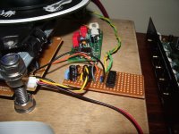
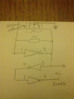
ok - sorry about the poor pic!this is what i am using now - this is really just the schematic that Peter Daniels posted - minus the bits that i either didn't need or didn't have!! - so mucho thanks to him again.
if you don't have an external clock cct then you'll need a crystal and 1M resistor across the first invertor like Peter's cct. When I tried using a crystal I didn't need the 22pF cap to ground either but I guess that might change depending on each crystal used.
The 2 i/c's are 74ACT14, a hex invertor and 74AS74, a dual flip-flop - you'll obviously need to supply a +5v feed and ground to both these chips together with some local decoupling. Like Peter i just used the +5v from the board too.
ok - sorry about the poor pic!
this is what i am using now - this is really just the schematic that Peter Daniels posted - minus the bits that i either didn't need or didn't have!! - so mucho thanks to him again.if you don't have an external clock cct then you'll need a crystal and 1M resistor across the first invertor like Peter's cct. When I tried using a crystal I didn't need the 22pF cap to ground either but I guess that might change depending on each crystal used.
The 2 i/c's are 74ACT14, a hex invertor and 74AS74, a dual flip-flop - you'll obviously need to supply a +5v feed and ground to both these chips together with some local decoupling. Like Peter i just used the +5v from the board too.
Attachments
I rebuilt the circuit as Peter scheme, but nothing, the same story. When I connect 74ACT14 pin6 to the clock on board everything stop working (remote control, door switch, LCD, dout from board). When it's disconnected the jvc board works but I don't get any proper signal from the reclocked output. I tried +5V from the board and from an external PS, the same.
Any suggestion?
The last attempt before giving up will be to swap the two ICs and the crystal with new ones.
Any suggestion?
The last attempt before giving up will be to swap the two ICs and the crystal with new ones.
reclocking probs
massimo - since your clock signal doesn't appear to be getting back to the main board then I would say 1 or more of the invertors is not working correctly.
I would try taking the clock output direct from pin1 firstly (ie. the same place as the clock input) - then try after the first invertor @ pin 2, then after 2 invertors @pin 4 and so on - if one of the first 3 invertors is caput then your clock signal obviously won't get back to the board - mine works OK no matter how many invertors i put the clock through before sending it back to the board. If you do find a busted one then you may have to re-route to use one of the spare ones instead - assuming the chip itself is not totally gone.
hope you get it sorted
As an aside I managed to get to the bottom of my occasional skipping/distortion problem - it was actually because I was still using breadboard and had too much wiring - it happened several times last night and when I touched the long data wires the problem would stop and it would play normally - I guess at these freqs it was radiating all over the place and causing problems - so I was up early this morning and got it put onto a piece of vero and kept the leads short. It's been stable now for a few hours so I'm confident that it's fixed.
massimo - since your clock signal doesn't appear to be getting back to the main board then I would say 1 or more of the invertors is not working correctly.
I would try taking the clock output direct from pin1 firstly (ie. the same place as the clock input) - then try after the first invertor @ pin 2, then after 2 invertors @pin 4 and so on - if one of the first 3 invertors is caput then your clock signal obviously won't get back to the board - mine works OK no matter how many invertors i put the clock through before sending it back to the board. If you do find a busted one then you may have to re-route to use one of the spare ones instead - assuming the chip itself is not totally gone.
hope you get it sorted
As an aside I managed to get to the bottom of my occasional skipping/distortion problem - it was actually because I was still using breadboard and had too much wiring
- it happened several times last night and when I touched the long data wires the problem would stop and it would play normally - I guess at these freqs it was radiating all over the place and causing problems - so I was up early this morning and got it put onto a piece of vero and kept the leads short. It's been stable now for a few hours so I'm confident that it's fixed.Attachments
Last edited:
Massimo - I've just re-read your post again ............
you say that when you disconnect the wire from pin 6 then the board works but you get no re-clocked data out? ............... well the board cannot work if you remove the clock from it ................................. unless you have the clock going direct to the board as well as through the invertors - and that will probably be why it stops working when you connect ANOTHER (slightly delayed and inverted!) clock from pin 6.
The clock must only get to the jvc board through this circuit.
Last edited:
The clock must only get to the jvc board through this circuit.
I missed the point and didn't remove the crystal on jvc board, thank you for this helpful hint.
I missed the point and didn't remove the crystal on jvc board, thank you for this helpful hint.
glad it was something simple - thought that would explain the problem. It should work now then
- I'm looking forward to hearing what you think about it.Hi Graeme
Thanks for posting your work on what appears to be the another good upgrade for the Shigaclone (how good can this thing get?).
While your schematic looks simple enough to implement, I'm a bit lost a couple of basic things:
I have left the original crystal in (on the main board) as per Peter's minimal mods discussed earlier - can I use the reclocker in this case or do I need an external crystal (with the resistor) such as the one shown in the photo on post #3853?
and:
Providing I can use the original crystal (or a relocated one), I'm not sure where exactly you connect up the reclocker to the board. From your schematic where exactly do the "from clock" and "To clock input on board" for the 74ACT14 connect to (on the main board).
If you are able to, some photo's would be great!
cheers
Tim
Thanks for posting your work on what appears to be the another good upgrade for the Shigaclone (how good can this thing get?
).While your schematic looks simple enough to implement, I'm a bit lost a couple of basic things:
I have left the original crystal in (on the main board) as per Peter's minimal mods discussed earlier - can I use the reclocker in this case or do I need an external crystal (with the resistor) such as the one shown in the photo on post #3853?
and:
Providing I can use the original crystal (or a relocated one), I'm not sure where exactly you connect up the reclocker to the board. From your schematic where exactly do the "from clock" and "To clock input on board" for the 74ACT14 connect to (on the main board).
If you are able to, some photo's would be great!
cheers
Tim
ok - sorry about the poor pic!
if you don't have an external clock cct then you'll need a crystal and 1M resistor across the first invertor like Peter's cct. When I tried using a crystal I didn't need the 22pF cap to ground either but I guess that might change depending on each crystal used.
The 2 i/c's are 74ACT14, a hex invertor and 74AS74, a dual flip-flop - you'll obviously need to supply a +5v feed and ground to both these chips together with some local decoupling. Like Peter i just used the +5v from the board too.
Last edited:
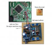
Tim - to use this circuit you do need to remove the original resonator from the board - you also need either a proper external clock circuit like a Tent/Trichord etc or a replacement crystal like the Citizen that Peter used in his original build ......................... but, it might be possible to use the original resonator in place of a new crystal in this circuit - this is a bit of an unknown until someone gives it a go - because the resonator has a couple of internal caps fitted it might not work so well.
the quick diagram I drew suggests that an external clock circuit will be used - hence 'clock input' to pin 1 of the hex invertor. If you intend to use a crystal or have a go with that resonator then you need to connect it and a 1Meg resistor across the first invertor (pins 1 & 2) of the 74act14 - if this sounds confusing look a few pages back for Peter's original re-clocking suggestion to see how to implement it properly. If you do have a go with the resonator then it's the outer pins that you want to use.
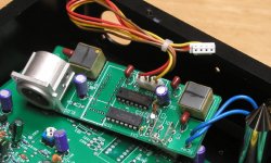
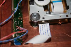
the 'clock output to board' goes back to the place where the original resonator would be connected - if the circuit is powered from the jvc board then you just need a single wire here - i've posted one of the many pics that illustrate this below.
that's it I think - once again, massive difference in my Shiga after fitting this - but again i must stress that i fitted a seperate external Tent clock at the same time as this circuit so your results could be different. It would be great to try that original resonator and see if it works - be useful for those without a new crystal or clock.
let us know how you get on
the quick diagram I drew suggests that an external clock circuit will be used - hence 'clock input' to pin 1 of the hex invertor. If you intend to use a crystal or have a go with that resonator then you need to connect it and a 1Meg resistor across the first invertor (pins 1 & 2) of the 74act14 - if this sounds confusing look a few pages back for Peter's original re-clocking suggestion to see how to implement it properly. If you do have a go with the resonator then it's the outer pins that you want to use.
the 'clock output to board' goes back to the place where the original resonator would be connected - if the circuit is powered from the jvc board then you just need a single wire here - i've posted one of the many pics that illustrate this below.
that's it I think - once again, massive difference in my Shiga after fitting this - but again i must stress that i fitted a seperate external Tent clock at the same time as this circuit so your results could be different. It would be great to try that original resonator and see if it works - be useful for those without a new crystal or clock.
let us know how you get on
Attachments
re-clock with original resonator
Ok guys I've just had a little play and tried the re-clocking circuit with the original resonator - and it works!!
I tried originally with just the outer pins across the invertor - both ways round (just in case!) and got it to read the TOC but not play. Then i tried tying the middle pin to ground, just as it is used on the jvc board - and it plays fine - I'm listening to it now on headphones. I can't really say if there is a substantial improvement or not - I'll listen to a full album first to make sure it is stable then refit the Tent and try to gauge the difference (if any!)
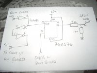
I've attached one of my professional drawings showing the invertor using the resonator! - this means that anyone without access to a replacement crystal or clock can still remove the resonator from their own board and at least have a go with the re-clocking circuit and see what they think
I think i remember someone saying that the resonator is actually directional and will only work one way round when fitted on the jvc board - if that's the case then it might also be directional in this circuit too - i haven't tried swapping it around since I got it to work - if you do have a go and don't have success then try swapping the pins over across the invertor.
Ok guys I've just had a little play and tried the re-clocking circuit with the original resonator - and it works!!
I tried originally with just the outer pins across the invertor - both ways round (just in case!) and got it to read the TOC but not play. Then i tried tying the middle pin to ground, just as it is used on the jvc board - and it plays fine - I'm listening to it now on headphones. I can't really say if there is a substantial improvement or not - I'll listen to a full album first to make sure it is stable then refit the Tent and try to gauge the difference (if any!)
I've attached one of my professional drawings showing the invertor using the resonator!
- this means that anyone without access to a replacement crystal or clock can still remove the resonator from their own board and at least have a go with the re-clocking circuit and see what they think I think i remember someone saying that the resonator is actually directional and will only work one way round when fitted on the jvc board - if that's the case then it might also be directional in this circuit too - i haven't tried swapping it around since I got it to work - if you do have a go and don't have success then try swapping the pins over across the invertor.
Attachments
Last edited:
massive difference in my Shiga after fitting this
Well for a guy who keeps breaking things and who squirts acetone all over the place, I don’t feel very qualified to comment so take the following with as many pinches of salt as you want.
In contrast to the extent of the improvements you have found with this mod, Peter's remarks were less categorical and he suggested it was a matter of taste.
I ask myself if at least some of the improvements you experienced could be coming from the fact that you took some critical components off the main board.
My reasoning is as follows:
Peter’s photos show that he has used very thick standoffs that will sit perfectly square to the base, both of them at identical heights. Also he has chosen (where does he find these things?) nice machined washers which will bolt the steel mechanism plate as parallel as possible to the copper base plate without introducing any bending or strain into the mechanism which could otherwise effect the way it vibrates.
In contrast, I used ordinary M6 bolts sitting in hand threaded holes with ordinary washers and with the top nuts as equal in height as I could get them. Although I drilled the holes in the copper base plate with a drill press so they should be vertical, I found that maintaining the same alignment while tapping the threads into the soft copper with hand tools was almost impossible. The end result is that the bolts do not sit exactly at right angles to the base plate and if I want the mechanism to sit level when everything is tightened down, then there are going to be all sorts of stresses and strains in there. Needless to say, the sound of my set-up is not great and I get very noticeable improvements by loosening the top nuts holding the mechanism.
I have not seen your assembly which may be as well made as Peter's, but I am definitely going to redo the mechanics of mine before contemplating any other mods.
Attachments
- Home
- Source & Line
- Digital Source
- Finally, an affordable CD Transport: the Shigaclone story