BTW, I posted the updated info on transport built here: http://www.diyaudio.com/forums/audio-sector/160373-cd-transport.html#post2068816
Excellent new thread Peter, very useful for beginners.
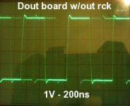
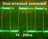
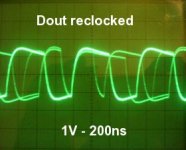
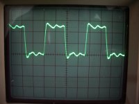
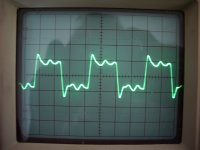
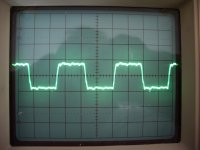
I tried the reclocking scheme you posted at #3786 but I got very messy dout signal. See pictures below: first dout from the board (pin 29 LC78601) with reclocking circuit not connected, second the same with reclocking circuit connected, third dout from the reclocking circuit.
Unfortunately I wasn't able to listen music through the reclocking cause for unknown (at least to me) reason, the remote control stop working and digits on LCD screen disappear when the reclocking circuit is connected. I tried many times with reclocking circuit on and off, but the same rule. It would be very interesting from a listening point of view to see if there's a difference between these two very different signals.
I'll try to build again the reclocking circuit from scratch to see if I get the same results.
Attachments
I built my first Shinga almost two years ago, and it is still sounds better than anything else I have. I wish I could build a second based on Peter's new suggestions, but can't find a source in the US. Anyone know of one or any of the Canadian fellow DIYers willing to send me one?
Thanks
JimS
Thanks
JimS
The reclocked signal is a lot lower than the others isn't it? Is this before or after the 300/100 resistors?
Fran
Yes it is, about 50%.
Before resistors.
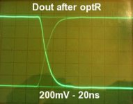
These are the signals after output resistors.
First pic is with reclocking circuit not connected (I'm sorry I lost 200ns pic)
Attachments
just to inform You all quickly...
i have finally (well, ALMOST") ) finished my Shigaclone... at least finally i have some pictures to show
) finished my Shigaclone... at least finally i have some pictures to show
here is the link:
- Shigaclone project (Pulse.Audio.Team)
still i would like to make Fetishizator for my digital output (power supply is allredy built in and waiting... i have used 2gr weight for the transport like Eric did but i think i will remove 1gr - i get some mechanical noises when my transport is going back to the start position (when finishing the cd) and it didn't do that before i put the weight there....
so i will cut the weight down to 1gr.....
i have to thank everybody that helped to build this fine thread... especially to Peter Daniel who started it.... thank You guys.....
i have finally (well, ALMOST
) finished my Shigaclone... at least finally i have some pictures to show here is the link:
- Shigaclone project (Pulse.Audio.Team)
still i would like to make Fetishizator for my digital output (power supply is allredy built in and waiting... i have used 2gr weight for the transport like Eric did but i think i will remove 1gr - i get some mechanical noises when my transport is going back to the start position (when finishing the cd) and it didn't do that before i put the weight there....
so i will cut the weight down to 1gr.....
i have to thank everybody that helped to build this fine thread... especially to Peter Daniel who started it.... thank You guys.....
http://products.nichicon.co.jp/en/pdf/XJA043/e-kz.pdf
Anyone try these as a replacement for the black gate caps in the power supply?
Anyone try these as a replacement for the black gate caps in the power supply?
http://products.nichicon.co.jp/en/pdf/XJA043/e-kz.pdf
Anyone try these as a replacement for the black gate caps in the power supply?
i have tried the "regular" cap's (what i had in my junk box)... also sounded nice... but BG's are better no doubt...

Those are the only two ceramic caps we need to remove, right?
Just double checking.
Merlin - nope, the one on the left is not a cap - it's a jumper!! - the RH one is correct - the other smd cap is 'round the corner to the left!' - have a closer look at the pics on Peter's posts - the 2nd smd cap is on the LH end of that chip - under the heatsink
Last edited:
Well I have had a right ball recently trying different things - in particular clocks!!!
I recently built a Ray/PFM Flea together with a Tent XO module -
it's supposed to be a pretty formidable clock module and supply, so I was expecting good things and was really looking forward to getting it connected up and hearing the marvellous music that SOME folk raved about after upgrading the resonator .................................................... well I have to say that the music changed dramatically once the Flea was connected .............................. for the worse!! - much worse. The bass disappeared altogether and the soundstage completely collapsed - it was thin, one-dimensional and just plain dull!! - to say I was miffed would be an understatement. I wonder how it is that some people get great results with aftermarket clocks and some get the opposite? - very strange.
So ................. the resonator goes back in and after a couple of days i thought I would give this a go -
it's a Harmony Electronics (google it!) crystal that I had on an old Arcam Alpha motherboard which has been sat in my parts bin for about 2 years now! - so in it goes - without any caps ................... and would you believe it - now this is what I was expecting from the Flea!!!  - more depth and interest from the music - with all the excitement of the shigaclone intact - yep, i thought - that will do nicely - cost £nil !!!
Now that would have been the end of the story - but Peter Daniel has a habit of posting up new ideas - so off I go again - this time I built Peter's re-clocking output circuit from post#3786. I just built it on breadboard - mainly to see if I could get it to work tbh. I used the old Arcam H.ele crystal without the 22pF cap to ground - I also don't have the pulse tranny so just split the final data output with the usual 300/100 resistors.
well - it worked ...................... and it worked well - very well actually!!! - imaging became seriously 3D - so I was super happy at that point as you can imagine ............................... for a while! unfortunately every few mins or so my Shiga would skip and mistrack - i thought maybe I needed the 22pF cap on the crystal like Peter's schematic but when fitted that stopped it tracking altogether. It was very peculier - working fine for a min or two then start skipping - then fine again for another min!! - weird. - not happy at this point.
Until ....................... I decide that I may as well try the Tent/Flea into the re-clocking circuit and see what happens ..................................... so I did.
OMG!!! - oh now this it what all those folks who got on with an aftermarket clock were raving about - this is now smooth, detailed, raw and exciting - all at the same time - the imaging is still quite stunning with a real 'walk through it' feeling - quite extraordinary - I am so pleased.
So that is where I am now - the Flea feeds Peter's output re-clocking circuit into pin 1 of the Hex invertor - which then also outputs to the DSP via a couple more of those invertors - amazing how this circuit has made such a difference - she has been playing for a few hours now and is steady as a rock.
Peter - you are a genius - everyone MUST MUST try this circuit - it cost almost nothing to implement - the pulse traffo does not seem to be essential - I kept the 0.1uF cap just in case there was some DC kicking about - then just divide the output as normal with your usual resistors. As Peter says - the sound is 'thicker' than normal with depth and texture in buckets. The low freqs especially now have real body - I'm 'feeling' kick drums much more now - I mean you can feel the air shifting in the room!!! - amazing.
Very happy indeed at the moment - it has been a good few days!! - can't wait to get that re-clocking cct built properly!!
Graeme
I recently built a Ray/PFM Flea together with a Tent XO module -
An externally hosted image should be here but it was not working when we last tested it.
it's supposed to be a pretty formidable clock module and supply, so I was expecting good things and was really looking forward to getting it connected up and hearing the marvellous music that SOME folk raved about after upgrading the resonator .................................................... well I have to say that the music changed dramatically once the Flea was connected .............................. for the worse!! - much worse. The bass disappeared altogether and the soundstage completely collapsed - it was thin, one-dimensional and just plain dull!!
- to say I was miffed would be an understatement. I wonder how it is that some people get great results with aftermarket clocks and some get the opposite? - very strange.So ................. the resonator goes back in and after a couple of days i thought I would give this a go -
An externally hosted image should be here but it was not working when we last tested it.
it's a Harmony Electronics (google it!) crystal that I had on an old Arcam Alpha motherboard which has been sat in my parts bin for about 2 years now!
- so in it goes - without any caps ................... and would you believe it - now this is what I was expecting from the Flea!!! - more depth and interest from the music - with all the excitement of the shigaclone intact - yep, i thought - that will do nicely - cost £nil !!!Now that would have been the end of the story - but Peter Daniel has a habit of posting up new ideas - so off I go again
- this time I built Peter's re-clocking output circuit from post#3786. I just built it on breadboard - mainly to see if I could get it to work tbh. I used the old Arcam H.ele crystal without the 22pF cap to ground - I also don't have the pulse tranny so just split the final data output with the usual 300/100 resistors.An externally hosted image should be here but it was not working when we last tested it.
well - it worked ...................... and it worked well - very well actually!!! - imaging became seriously 3D - so I was super happy at that point as you can imagine
............................... for a while! unfortunately every few mins or so my Shiga would skip and mistrack - i thought maybe I needed the 22pF cap on the crystal like Peter's schematic but when fitted that stopped it tracking altogether. It was very peculier - working fine for a min or two then start skipping - then fine again for another min!! - weird. - not happy at this point.Until ....................... I decide that I may as well try the Tent/Flea into the re-clocking circuit and see what happens ..................................... so I did.
OMG!!!
- oh now this it what all those folks who got on with an aftermarket clock were raving about - this is now smooth, detailed, raw and exciting - all at the same time - the imaging is still quite stunning with a real 'walk through it' feeling - quite extraordinary - I am so pleased.An externally hosted image should be here but it was not working when we last tested it.
So that is where I am now - the Flea feeds Peter's output re-clocking circuit into pin 1 of the Hex invertor - which then also outputs to the DSP via a couple more of those invertors - amazing how this circuit has made such a difference
- she has been playing for a few hours now and is steady as a rock.Peter - you are a genius - everyone MUST MUST try this circuit - it cost almost nothing to implement - the pulse traffo does not seem to be essential - I kept the 0.1uF cap just in case there was some DC kicking about - then just divide the output as normal with your usual resistors. As Peter says - the sound is 'thicker' than normal with depth and texture in buckets. The low freqs especially now have real body - I'm 'feeling' kick drums much more now - I mean you can feel the air shifting in the room!!! - amazing.
Very happy indeed at the moment - it has been a good few days!!
- can't wait to get that re-clocking cct built properly!!Graeme
Last edited:
Oops - used the wrong pic!
this was the re-clocker with the crystal -
it was actually very good indeed apart from the intermittant skipping which I may have been able to sort out if I hadn't reached for the Flea so quickly!! - i think it may be a voltage level thing - i guess the invertor outputs a TTL level - not a 3.5Vpp like the Flea - should scope it really but right now I'm in the sweet spot and enjoying some Eagles!!
Seriously guys - you all have to try this re-clocker. Never have I heard my CD's sounding like this - I am using a modified Beresford Caiman DAC with a Puresound A30 and a pair of Triangle Ittohs - even in my small-ish living room it has become almost holographic and the midband transparency is just breathtaking!!
Once again a huge thank you to Peter and all the regular contributors to this thread.
PS - how do you load up thumbnails rather than the full image??
this was the re-clocker with the crystal -
An externally hosted image should be here but it was not working when we last tested it.
it was actually very good indeed apart from the intermittant skipping which I may have been able to sort out if I hadn't reached for the Flea so quickly!! - i think it may be a voltage level thing - i guess the invertor outputs a TTL level - not a 3.5Vpp like the Flea - should scope it really but right now I'm in the sweet spot and enjoying some Eagles!!
Seriously guys - you all have to try this re-clocker. Never have I heard my CD's sounding like this - I am using a modified Beresford Caiman DAC with a Puresound A30 and a pair of Triangle Ittohs - even in my small-ish living room it has become almost holographic and the midband transparency is just breathtaking!!
Once again a huge thank you to Peter and all the regular contributors to this thread.
PS - how do you load up thumbnails rather than the full image??
Last edited:
Seriously guys - you all have to try this re-clocker. Never have I heard my CD's sounding like this
Interesting. Can you check the dout reclocked signal with a scope and confront it with the dout from the jvc board? Unfortunately I'm not able to listen the dout reclocked at this point for the problems I mentioned some posts ago. I'm very curious to see if you see a clean signal or a messy one like mine.
PS - how do you load up thumbnails rather than the full image??
look at post #3810
http://www.diyaudio.com/forums/digi...ansport-shigaclone-story-381.html#post2029090
Interesting. Can you check the dout reclocked signal with a scope and confront it with the dout from the jvc board? Unfortunately I'm not able to listen the dout reclocked at this point for the problems I mentioned some posts ago. I'm very curious to see if you see a clean signal or a messy one like mine.
massimo - I'll take it back upstairs tomorrow and take some scope pics for you - for now I'm engrossed with my Shiga again
- I know it's a cliche to say that it is like rediscovering your Cd's all over again - but it really has made me sit up and smile so many times since I connected this re-clocker and Flea.Of course, I don't actually know whether this difference has come about because of getting the new clock to gel with the DSP or the re-clocking circuit - or a combination of both!
I have re-read much of this fabulous thread again tonight and it seems that I am not the only one who has had disappointing results using a bare Tent XO straight into the DSP. Other clock modules seem to have faired better - that is not to suggest that the Tent XO's are inferior at all but possibly there is some impedance mismatch with this particular chip maybe? - I fitted 47R on the clock output when I built it as that was suggested to be a middle ground value - perhaps it would have worked better on it's own with a different output load R?? - right now I don't care to try - it is gelling now that's for sure and I just want to listen to it
As for my thumbnail question - so i upload pics direct to DIYA rather than a 3rd party hosting site? then they will appear as thumbnails? Y/N?
Last edited:
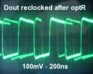
Reclocking traces
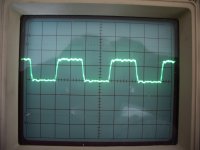
Ok - here are the traces from my Shiga - from the left.........
1. the Dout straight from the board (2V/200nS)
2. the output from the re-clocking cct (before R divider - 2V/200nS)
3. the final output after 300/100R divider (0.5V/200nS) the resistors seem to have cleaned up the pulse really well too - both are Kiwame 1W jobs. I notice the level is a little low mind - only about 0.7Vpp.
the 0V horizontal is centre on all traces - I noticed that because of the 0.1uF cap on the re-clocker o/p the final output is centred about 0V rather than being a purely positive going pulse - wasn't sure that this should be so - maybe someone does - Peter?
anyway I removed the 0.1u and took the output straight from pin 9 of the flip-flop - this is trace 4 - it is now a purely positive going pulse, again at 0.5V/200nS. A quick listen and it doesn't seem to have affected the sound - I think my Caiman has a 'pulse shaper' buffer type thing on the input anyway so it is probably taken care of there.
One thing i did notice Peter - if I take the MCLK back to the main board after 3 invertors (pin 6) then I still get the occasional skip and distortion - but if I just use 2 invertors (pin 4) or 1 invertor (pin 2) then it will work just fine - I've listened to it now using either 1 or 2 invertors for several hours and it's stable. Any ideas why this might be happening? Why did you suggest 3 invertors on the original cct? - was it a timing issue ? - sorry for all the questions - I'm hoping to learn something here!
Ok - here are the traces from my Shiga - from the left.........
1. the Dout straight from the board (2V/200nS)
2. the output from the re-clocking cct (before R divider - 2V/200nS)
3. the final output after 300/100R divider (0.5V/200nS) the resistors seem to have cleaned up the pulse really well too - both are Kiwame 1W jobs. I notice the level is a little low mind - only about 0.7Vpp.
the 0V horizontal is centre on all traces - I noticed that because of the 0.1uF cap on the re-clocker o/p the final output is centred about 0V rather than being a purely positive going pulse - wasn't sure that this should be so -
maybe someone does - Peter?anyway I removed the 0.1u and took the output straight from pin 9 of the flip-flop - this is trace 4 - it is now a purely positive going pulse, again at 0.5V/200nS. A quick listen and it doesn't seem to have affected the sound - I think my Caiman has a 'pulse shaper' buffer type thing on the input anyway so it is probably taken care of there.
One thing i did notice Peter - if I take the MCLK back to the main board after 3 invertors (pin 6) then I still get the occasional skip and distortion - but if I just use 2 invertors (pin 4) or 1 invertor (pin 2) then it will work just fine - I've listened to it now using either 1 or 2 invertors for several hours and it's stable. Any ideas why this might be happening? Why did you suggest 3 invertors on the original cct? - was it a timing issue ? - sorry for all the questions - I'm hoping to learn something here!
Attachments
Last edited:
Would be more interesting to watch the trace at the DAC side - that side is important one not the shiga side. I've found that tuning the shiga out and DAC in impedances (simultaneously - by changing resistors) is crucial, and what's mostly interesting: what you see at DAC side reflects very much what you hear
- Home
- Source & Line
- Digital Source
- Finally, an affordable CD Transport: the Shigaclone story