Hi Mark
Thanks bud
Yes, I ran this through LTSpice and noticed the attenuation as you mentioned with the FET. I decided to lash up and Opamp buffer with with 100% feedback based on a TL071 that I have to record the signal. I am hoping to do this sometime on the weekend and so I will let you know how I get on
Cheers
Ray
Hi all
Well I had to shelve this project for what I thought would be a couple of weeks and it turned out to be 6 months!!!!
So I am back on (Oh dear I hear you sigh!!!). I am very interested in measuring the output of the pickup dry to see what the peak voltages are under say really heavy strumming so that I can see that the preamp has enough head room. Markus mentioned measuring it via a sound recording and then using Wavelab etc to look at the signal. This sound ideal as I do not have a storage scope. I have built a simple op-amp buffer that has unity gain and the correct input impedance.
My question is, how can I be sure that the signal getting in to the soundcard is also at unity gain as there are a number of volume controls that need setting on the PC, both in Windows and the recording software. What settings do I use on these mixers to ensure my signal is not amplified (or indeed attenuated) in any way when I record?
Cheers
Ray
Ray,MondyT said:What settings do I use on these mixers to ensure my signal is not amplified (or indeed attenuated) in any way when I record?
Cheers
Ray
Usually a sound card that is slightly more advanced than a very basic sound card has a kind of control panel, in which you can set various parameters. If you have such a panel, you can set Recording Gain = 0 dB.
If you have some other signal source (e.g. signal generator), you can verify that the recorded signal id not amplified. Just measure the signal with a multimeter, record it and verify that you have the same signal level in software you use.
Mark
AMZ wondering if
Hi there, im very new to electronics but being a electrician have a little basic understanding, anyhow a question for your good self, I have fitted a belcat piezo under bridge pickup to my fender dg 22 but unfortuately not enough output to drive the valvestate 8040 front end so do you think that something like the AMZ would do it and would it be possible to come out of end pin jack socket I fitted into a short screened cable then into a plastic box clipped to my guitar strap with the AMZ circuit and 9v battery inside, then 1/4 inch jack lead back to the marshall. sorry to bother you with more questions rather than answers, I am enrolling on a electronics course in sept 09 so I should get wiser sometime in the future! in the mean time sorry for my stupidness, regards simon.
Hi there, im very new to electronics but being a electrician have a little basic understanding, anyhow a question for your good self, I have fitted a belcat piezo under bridge pickup to my fender dg 22 but unfortuately not enough output to drive the valvestate 8040 front end so do you think that something like the AMZ would do it and would it be possible to come out of end pin jack socket I fitted into a short screened cable then into a plastic box clipped to my guitar strap with the AMZ circuit and 9v battery inside, then 1/4 inch jack lead back to the marshall. sorry to bother you with more questions rather than answers, I am enrolling on a electronics course in sept 09 so I should get wiser sometime in the future! in the mean time sorry for my stupidness, regards simon.
Hi Simon
No worries my man, your question is not stupid at all. Fortunately for both of us, there are a great number of really knowledgeable and helpful people on this forum and without them, my project would not have got of from the get go as my knowledge in these matters was pretty slim. I have learned loads here!!
OK I cannot find any specs on the Belcat UST pickup but I am pretty sure that the circuit(s) presented here should do the trick as an interface between your pickup and your Marshall. The most important thing to establish is the output impedance of the pickup. Most under saddle systems are high impedance and in the order of 5 to 10Mohms is required. This is fine for the FET inputs shown in these circuits as the input impedance of the FET is far higher than this and therefore the input impedance can be set by changing the value of the input resistor (the one connected between to the 1st FET source pin and ground). If your pickup has an output of 10Meg ohms, then a 10Meg Ohm resistor should be chosen.
The pickup I use is unusual in that it has a lower output impedance of 1.0Meg Ohm and therefore I needed a custom preamp.
I would not however use a plastic box as these circuits are high impedance and low level and so will be very prone to pickup of electrical noise. You will need a metal case and the ground of your preamp circuit should be bonded to this case.
As you are going into a valve amp (valve input stage at least?), most of the sonic characteristics of FETs will be already in your amp circuitry and therefore you may be better off going with a simple Op-amp based preamp circuit rather than the FET based ones
Cheers
Ray
AMZ
Many thanks for reply, got some good points there about the plastic box as I recall a friend did some work on his gordon smith electric and ended up with bad almost static sounds and was down to the plastic scratch plate he fitted along with alternative pickups and had to line out body cavity and back of scratch plate with sticky foil to ground out unwanted noise, also the front end of the marshall is tube, a single ecc83 I think, so maybe I should be looking op-amp,,,Any suggestions circuits or devices? Have drawn a vero board layout using AMZ components but guess I could do same for other circuits as well as its interesting trying make it as small as possible for application intended. Again thanks for help. Regards Simon.
Many thanks for reply, got some good points there about the plastic box as I recall a friend did some work on his gordon smith electric and ended up with bad almost static sounds and was down to the plastic scratch plate he fitted along with alternative pickups and had to line out body cavity and back of scratch plate with sticky foil to ground out unwanted noise, also the front end of the marshall is tube, a single ecc83 I think, so maybe I should be looking op-amp,,,Any suggestions circuits or devices? Have drawn a vero board layout using AMZ components but guess I could do same for other circuits as well as its interesting trying make it as small as possible for application intended. Again thanks for help. Regards Simon.
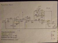
I have now modified/redesignedthis piezo disc preamp from the original circuit which was published in http://www.redcircuits.com on page 16,but I never managed to get it working with a piezo disc!May be I overlooked something?
The mods & additions to the original circuit are as follows:
1.A high impedance non-inverting JFET buffer was added.
2.All ICs changed to TL072 (use only JFETs)
3. Circuit was modified for (dual) +/- 9v battary supply..sounds more spacier!
PIEZO DISC
Diameter - 20mm
Capacitance - 14nF +/- 30%
Resonance Freq; - 6kHz +/- 0.5%
Resonance Imped- 200 (unit not specified)
The placement of the "disc" evidently seems very critical for optimum sound.It works extremely well only on the "sweet spot" & sounds almost realistically acoustic.
Attaching/fitting the the disc directly on to the guitar changes the sound drastically,when the volume pot is turned more than half way up.placing a small piece of masking tape between the disc & the guitar & then masking the whole disc seems to cure the problem,albeit with a little softer sound.
Doesn't seem to work well with USTs at all...uhh
There are still a few niggles with this circuit..but promises to be the best sounding piezo preamp so far.. at least to my ears!
I'm not sure if I have calculated the values for the 2nd stage properly or not! So, please do point out any oversight on my part,& any improvements to this circuit would be most welcome.
Thanks.
Attachments
Hi All
Well I finally found some time to get down to recording my guitar pickup output as Markus kindly suggested so that I can check the preamp circuit in LTSpice and assign a realistic input voltage.
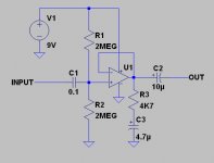
I knocked up the circuit below using a TL071 op-amp to provide a unity gain 1MegOhm buffer for the pickup (attached). I connected the output to my Audigy Platinum II soundcard and used Wavelab to record the output. I then strummed the guitar pretty much as loud as I could and the resulting audio WAV file I saved is here…
Guitar Test File
I ran an analysis on the WAV file using Wavelab (bearing in mind that I am not 100% sure of what I am doing!) and it showed that the file had a highest peak amplitude of -12.36dB. So am I right in thinking if this was dBV then this would equate to the input having a peak voltage of around 680mV?
If this is true and I am using LTSpice correctly, I cannot input 680mV pk at 1Khz without getting bad clipping of the output. The LTSpice schematic is here...
FET Preamp circuit
Can anyone verify if any of this has any bearing on fact and if my thoughts and findings are correct, or I am badly off track!?
Cheers
Ray
Well I finally found some time to get down to recording my guitar pickup output as Markus kindly suggested so that I can check the preamp circuit in LTSpice and assign a realistic input voltage.
I knocked up the circuit below using a TL071 op-amp to provide a unity gain 1MegOhm buffer for the pickup (attached). I connected the output to my Audigy Platinum II soundcard and used Wavelab to record the output. I then strummed the guitar pretty much as loud as I could and the resulting audio WAV file I saved is here…
Guitar Test File
I ran an analysis on the WAV file using Wavelab (bearing in mind that I am not 100% sure of what I am doing!) and it showed that the file had a highest peak amplitude of -12.36dB. So am I right in thinking if this was dBV then this would equate to the input having a peak voltage of around 680mV?
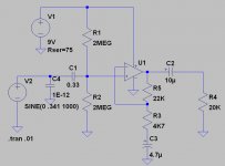
If this is true and I am using LTSpice correctly, I cannot input 680mV pk at 1Khz without getting bad clipping of the output. The LTSpice schematic is here...
FET Preamp circuit
Can anyone verify if any of this has any bearing on fact and if my thoughts and findings are correct, or I am badly off track!?
Cheers
Ray
Ray,
I don't have any audio software at work but at least according to this decibel converter: http://www.mogami.com/e/cad/db.html -12.36dB gives 0.24V amplitude of the signal. This will still cause some distortion in your simulation but you can decrease the gain of the preamp by decreasing R2 resistor value from 43k to 15k. Then, you get 600mV signal amplitude on the output of the preamp (which should be fine for the sound card input).
You can also increase the power supply to 18V but then the amplitude of the signal will be 1.5V, which will be too much for the sound card.
PS: the C3 capacitor and the R3 resistor are not needed in the buffer.
I also think that in Wavelab you can directly measure the amplitude both in dB and mV (so you don't need any dB converter).
Mark
Hi Markus
Thanks buddy! Yes I forgot to add that 680mV is Pk-Pk and therefore 0.24rms would be right.
I looked in Wavelab and there only seemed to be an option to display the Audio on a scale of %, dB or decimal. I couldn't find voltage anywhere??
I was playing around with the gain of the buffer and so I used the resistor and cap and left it there when connecting for 100% feedback, unity gain.
I will have a play around using 0.34v pk input and see if I can get it to behave by changing resistor values as you suggest.
Cheers
Ray
G'day MontyT,
I too have been struggling with a piezo disc preamp ...until I started researching/reading endlessly on this subject. I am still no expert by any stretch of the imagination, however I think I'm getting some idea of these little creatures(piezos I mean) at last!
Firstly,looking at your "circuit" I am impressed that you'd got some sound through it at all. I too started with an inverting buffer..but my Roland 60AC acoustic combo wouldn't take kindly to it-severe loading effect!
As Markus2006 has already pointed out, you don't need either C3 or R3 in the circuit.
If you need more gain,then you could perhaps add a feed-back loop to the circuit? say, with a gain of 2 (3dB) should give you enough (drive) signal. If you decide to include a feedback loop, then it would be a good idea to add these 2 values/2 (divide) & connect this value R in in series with the input cap, to compensate for any loading effect at the input.
As I listened to the sound sample,I wasn't sure if it was an acoustic or e.guitar you were playing through the preamp,since I couldn't hear any freq; I guess, below 250-300 Hz region!!
(what -3dB point does the LT SPICE show?)
You'd need a decent signal level to drive/ obtain a resonable low frequncy range from on about 100Hz at least around the -3dB point. If I remember correctly the lower "E" on a guitar is 84Hz?
Acoustic guitars in my view, behave so unlike electric guitars through amps. You'd need ahigh enough gain ie;dynamic range in your preamp in order to get a good frequency response.
In my humble opinion, running it on a single 9V supply doesn't help matters much either. Have you ever considered running it on 9+/-9 battary supply?
(I too made this mistake..until..I saw a great burning bush.....")
Try changing C1 to say,1uF non polar cap..You should then get a little better Lo freq; response.
Which op-amp are U using in this circuit? If U'r using a Piezo disc or PVDP film or similar then use,
1. A JFET opamp with a VERY HIGH input impedance.(Resistance)
2. VERY LOW BIAS current device.
The difference is like day & night.
It became a magical transformation when I connected my piezo disc to a "Charge Amplifier" instead, before the i/p buffer.
It is quite similar to u'r invert opamp circuit,but with a Res. & a Cap in parallel in the feedback loop."R" on a charge amp should be around 10M at least."C" determines the gain.
This feedback cap only determines the gain of the "Charge" amp.You could run it either on a single or +/- battary...I don't think it's worthwhile sparing a battary to the detriment of sound quality!
I too have been struggling with a piezo disc preamp ...until I started researching/reading endlessly on this subject. I am still no expert by any stretch of the imagination, however I think I'm getting some idea of these little creatures(piezos I mean) at last!
Firstly,looking at your "circuit" I am impressed that you'd got some sound through it at all. I too started with an inverting buffer..but my Roland 60AC acoustic combo wouldn't take kindly to it-severe loading effect!
As Markus2006 has already pointed out, you don't need either C3 or R3 in the circuit.
If you need more gain,then you could perhaps add a feed-back loop to the circuit? say, with a gain of 2 (3dB) should give you enough (drive) signal. If you decide to include a feedback loop, then it would be a good idea to add these 2 values/2 (divide) & connect this value R in in series with the input cap, to compensate for any loading effect at the input.
As I listened to the sound sample,I wasn't sure if it was an acoustic or e.guitar you were playing through the preamp,since I couldn't hear any freq; I guess, below 250-300 Hz region!!
(what -3dB point does the LT SPICE show?)
You'd need a decent signal level to drive/ obtain a resonable low frequncy range from on about 100Hz at least around the -3dB point. If I remember correctly the lower "E" on a guitar is 84Hz?
Acoustic guitars in my view, behave so unlike electric guitars through amps. You'd need ahigh enough gain ie;dynamic range in your preamp in order to get a good frequency response.
In my humble opinion, running it on a single 9V supply doesn't help matters much either. Have you ever considered running it on 9+/-9 battary supply?
(I too made this mistake..until..I saw a great burning bush.....
Try changing C1 to say,1uF non polar cap..You should then get a little better Lo freq; response.
Which op-amp are U using in this circuit? If U'r using a Piezo disc or PVDP film or similar then use,
1. A JFET opamp with a VERY HIGH input impedance.(Resistance)
2. VERY LOW BIAS current device.
The difference is like day & night.
It became a magical transformation when I connected my piezo disc to a "Charge Amplifier" instead, before the i/p buffer.
It is quite similar to u'r invert opamp circuit,but with a Res. & a Cap in parallel in the feedback loop."R" on a charge amp should be around 10M at least."C" determines the gain.
This feedback cap only determines the gain of the "Charge" amp.You could run it either on a single or +/- battary...I don't think it's worthwhile sparing a battary to the detriment of sound quality!
Teleman,
You haven't read the thread. Ray with the opamp buffer (with unity gain) tries to measure the signal level from the piezo pickup. And the final preamp will be based on JFET transistor (which SPICE simulation is included in the previous post).
BTW, what exactly is "Charge Amplifier" and how can a capacitor determine its gain? I haven't heard about such amps. Can you post a schematic of such amp?
Mark
Hi Markus,
Yes, you're right! I haven't been following all of MontyT's posts!
I think I totally missed the goal post ...sorry too about the long winded sermon 'bout the design.
I too built & tried a similar circuit...but when I loaded it to the rest of the circuit shown elsewhere in this coloumn, & connected to my Roland AC60 ac.amp,that's when all the problems started.
As you may readily admit loading on a PC & real life are totally 2 different things.even with my very limited knowledge/experience with piezos.(I'm not really sure if this was only due to my Roland AC60 ac.amp or not.)
The most obvious one was the severe loading & the other was the piezo charging/discharging!(The sound gets weeker by the minute. But then the charge amp changed all that!
Please find an attachment of the "Charge amp" circuit kindly provided by "Phaseacurate"..which was quite revealing, at least
on my preamp!
Attachments
![chargeamp[1].gif](/community/data/attachments/128/128721-c3f3d77746c51852f6ec7eb34ff376c8.jpg)
Hi
Thanks both for your replies and help!
As Markus explained, the object of the exercise was to measure the output of my pickup (no storage scope available) and that is why I built the buffer. I believe the 4.7uF cap and the 4.K7 resistor in the op-amp buffer is for a bit of “hum” filtering in the orginal circuit I found, could be wrong though! I must admit Teleman, the audio clip does sound pretty awful but it is an acoustic guitar, I promise!
I played around with the FET circuit in LTSpice and it just looks like I am not going to be able to get sufficient gain out of this circuit to run the Line Input of my mixer adequately without distortion. I think I would need around 700mV to 800mV so that I can run this input without having the gain on the Line Input flat out (I am trying to aim for adequate volume without turning the level knob past 12oclock) I am going to build the circuit and check it just in case, but I have a sneaky feeling the LTSpice is not going to be far off
I started playing with the op-amp buffer last night and was quite surprised with the results. I can get plenty of gain out of it and the sound is pretty darned good with a TL071 op-amp!! I made the changes in the attached circuit and run the guitar into this and the output into my soundcard whilst listening back to the soundcard via phones. This sounded very sweet indeed with bags of gain, and so If the FET version does not work out, I may go for this instead (dare I say it!!)
Looking at your circuit Teleman, I would say that the input to this circuit is too low impedance for piezo elements (235K?). My system uses 3x piezo elements wired in parallel and therefore needs a lower input impedance of 1.0Meg than most. Most piezo elements and under saddle units require around 5 to 10Meg inputs to get the full frequency response. I could be wrong though and I am sure my mentor Markus will put us both right!!
The single 9v battery versus dual 9v battery issue is a good one. It has always been my experience with gigs that the minimum amount of batteries to go flat at the wrong time, is the aim and the average petrol station or late night store, that you end up having to dash to, always seem to stock the expensive Duracell versions if they stock them at all, and so 1 battery is a good thing. However, I am impressed with the sound I was getting last night and so if you feel that a +/-9v supply would improve this further, then I am interested to say the least. I am thinking maybe installing 2 x NiMH batteries and having a charge socket on the preamp. Problem is, I have no idea how to modify the circuit attached to operate of a dual supply, could you guys help me? Even using the circuit as it is, I would be interested on any mods you or Markus recommend to make the circuit practical for use as a preamp for gigs without altering the sound of the basic circuit
Cheers
Ray
Attachments
Hi MontyT,
As for getting high enough gain,it's not a good practice to beef up the buffer stage with very high gain!You will encounter all sorts of problems.That's why as you may have already observed many such designs have different gain stages,so as not to inroduce noise, distortion & feedback.
This would of course require a some gain in the feedback loop, especially with the opamp design you have!
Loading into a very low impedance head phones & plugging in to a very high impedance guitar amp are entirely two different things as you may soon find out!(sorry if I sounded an..........)
I think you've completely "misread" my "circuit". It's not a buffer as you (may) have concluded, but a "CHARGER".
As for running on a single battary,I never liked the idea..after hearing most og the ac.preamps out there.Dual supply is the way to go,especially if you want the real acoustic sound.This is my own experience.
I've found that "Smoke detector/alarm - Lithium battaries have a colossal capacity-1200mAh with very little leakage & a long shelf life too. Although they are a bit pricy you'd be able to pick them cheaper @ A$9-10 doller a piece..& they are worth it. I've been using the same ones since Dec.last year...still going...
Btw connecting a 100uF/25-35v or so elec.capacitor to ground on each rail would prolong battary life, since this will prevent battaries discharging suddenly due to high impedance loading of the circuit.
Hi Teleman
Thanks for your reply. I am not too sure what you mean by a Charger circuit for piezos, probably way above my head my friend!
I outputted the circuit into my mixer Line input and then the output from the mixer went to the AUX input on my sound card, the phones were connected to the headphone socket on the sound card and therefore not being used as a load on the circuit. Sounded really good and so I am hoping it will be the same when I connect it up to my main PA amp (t'was too late at night to try, but maybe on the weekend, the neighbours may just help me with my evaluation!)
How can I modify my op-amp circuit I have for a dual supply as you have me hooked and I just have to try it out now!!!
Cheers
Ray
- Status
- This old topic is closed. If you want to reopen this topic, contact a moderator using the "Report Post" button.
- Home
- Live Sound
- Instruments and Amps
- FET based Acoustic preamp help