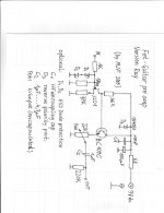
Since the transistor works in the "emitter follower" configuration (check http://en.wikipedia.org/wiki/Common_collector for details), you can use any small signal NPN bipolar transistor; e.g. BC549C. But check the pins of the transistor you are going to use - 2N5088 has E-B-C, whereas BC549 has C-B-E. Looking at the description of the emitter follower you can see that the higher hfe coefficient, the better parameters of the circuit. You may also take a look at the way the input and output impedance is calculated. It looks like you can try 100k output resistor (because actual output impedance depends greatly of the hfe coefficient of the transistor and it's not 100k as it seems).MondyT said:Should I have problems sourcing the 2N5088 transistors, could say a BC109C or similar transistor be used here or would this mean changes in the component values and problems with output impedance etc?
Mark
Should I have problems sourcing the 2N5088 transistors, could say a BC109C or similar transistor be used here or would this mean changes in the component values and problems with output impedance etc?
hello.
the 2n5088 is a low noise type with high hfe-values.you can change it to a similar trans. like bc109c,bc549c,bc550c,...........without problems.
greetings...................
hello.
the 2n5088 is a low noise type with high hfe-values.you can change it to a similar trans. like bc109c,bc549c,bc550c,...........without problems.
greetings...................
Markus2006 said:It looks like you can try 100k output resistor (because actual output impedance depends greatly of the hfe coefficient of the transistor and it's not 100k as it seems).
No, it's not 100K, but it's not going to be at all low either - certainly FAR too high to feed a 20K input.
OK, had a little spare time at work, so I built the emitter follower stage 
As I suspected, you can't actually measure the output impedance, because the stage doesn't work in that way. But I would STRONGLY suggest you assume the output impedance is the same value as the emitter resistor, and keep any load at least four or five times higher than the emitter resistor value.
With 1KHz 1V p-p going through it, a BC109, a 100K emitter resistor, and a 20K load, the output negative excursions are heavily reduced, and actually clip, giving massive distortion. The positive excursions are pretty well unaffected (at least visually on a scope), which is what you would expect of the stage with a 100K emitter resistor.
Basically on positive excursions the output capacitor is charged by the transistor current (low impedance), and on negative excursions it's discharged by the emitter resistor (high impedance), this makes the output asymmetrical giving high distortion.
Hi Nigel
Many thanks for your time and effort my man!! This is much appreciated and the outcome is very interesting and helpful.
So basically I need to reduce the emitter resistor to reduce the output impedance and the maximum for a match would be around 4.7K (this could be handy as it is a common pot size should I need a variable output) but ideally lower for a 20K load.
2.2K I suppose would be ideal but what would this do to the circuits current consumption and will this value upset other circuit parameters?
Once again many thanks to you!
Cheers
Ray
Output impedance details
I attach the plot of the preamp output impedance with BC547C and 10k output resistor. As you can see it's more or less 130 Ohms.
Other options:
- BC547A -> 240 Ohms,
- 33k -> 270 Ohms,
- 4.7k -> 100 Ohm.
You can get the best results with BC547C (or other high gain transistor) and 4.7k resistor. But I suggest 10k resistor to keep the battery consumption low. With 10k you get 0.53mA current which will keep your battery alive for a long time.
It's important to understand that the output impedance is not that much related to the output resistor but rather to the previous stage output impedance and to the transistor's hfe coefficient.
Mark
Attachments
I'm sorry but you are wrong. Output impedance of a emitter follower is explained here: http://en.wikipedia.org/wiki/Common_collectorNigel Goodwin said:I would suggest your simulator is completely useless!
How is a 10K resistor going to discharge a 4.7uF via an impedance of 130 ohms?.
The charging of the capacitor may well be from 130 ohms, but the discharge certainly won't be, as it's simply through the resistor.
Here you can find precise calculations (if you want to repeat them): http://books.google.pl/books?id=EEc...X&oi=book_result&resnum=2&ct=result#PPA103,M1
Here you have an example (mic output impedance = 270 Ohms is reduced to 3 Ohms output impedance - and emitter resistor is 3.3k in this case):
http://mxp.physics.umn.edu/f03/Lecture/lecture 09-17.pdf
Since this is lecture from the University of Minnesota (physics department) I wouldn't argue to much with it.
The most important fact is that the output impedance of the previous stage is reduced by a factor equal to the transistor current gain. And the emitter resistor almost doesn't count (see the calculations).
If all these people are wrong, I would notify them that they are teaching students incorrectly (especially in Minnesota).
What you are saying would be true, if not the gain of the transistor. Please check the calculations and tell me whether you see there any error.
Mark
Markus2006 said:I'm sorry but you are wrong. Output impedance of a emitter follower is explained here: http://en.wikipedia.org/wiki/Common_collector
Here you can find precise calculations (if you want to repeat them): http://books.google.pl/books?id=EEc...X&oi=book_result&resnum=2&ct=result#PPA103,M1
Here you have an example (mic output impedance = 270 Ohms is reduced to 3 Ohms output impedance - and emitter resistor is 3.3k in this case):
http://mxp.physics.umn.edu/f03/Lecture/lecture 09-17.pdf
Since this is lecture from the University of Minnesota (physics department) I wouldn't argue to much with it.
The most important fact is that the output impedance of the previous stage is reduced by a factor equal to the transistor current gain. And the emitter resistor almost doesn't count (see the calculations).
If all these people are wrong, I would notify them that they are teaching students incorrectly (especially in Minnesota).
What you are saying would be true, if not the gain of the transistor. Please check the calculations and tell me whether you see there any error.
Mark
Please tell me where the current to discharge the output coupling capacitor comes from on negative excursions?.
I actually built the buffer stage and tested it - it doesn't work - try it yourself (100K emitter resistor, 4.7uF capacitor, a 20K load on the output, and 1V p-p 1KHz). As you (or at least I) would expect with no fast discharge path for the capacitor it distorts and actually clips on negative peaks.
I'd be more impressed with lecture notes from an Electronics course rather than a Physics one, and Minnesota means absoutely nothing to me
None of the links you posted are actual working circuits, they are purely theoretical, so don't have the OUTPUT COUPLING CAPACITOR. Without it the load is in parallel with the emitter resistor, and the emitter resistor isn't 100K any more.
I can only confirm that with 100k emitter resistor, 4.7uF capacitor and 20k load there will be distortion. I got exactly the same results with my "poor" simulator (which is LTSpice - one of the best on the market). But we already said that with 20k load, the emitter resistor should be decrased (you suggested 4.7k and I suggested 10k). Then, there is no need for 4.7uF capacitor on the output. You will get very good results with 1uF (it was verified with the simulator). Please remember that a typical input impedance of a guitar amp is usually higher than 500k. And in such a case the preamp works correctly (even with 100k emitter resistor), both with signal generator/osciloscope and on stage.Nigel Goodwin said:..I actually built the buffer stage and tested it - it doesn't work - try it yourself (100K emitter resistor, 4.7uF capacitor, a 20K load on the output, and 1V p-p 1KHz). As you (or at least I) would expect with no fast discharge path for the capacitor it distorts and actually clips on negative peaks.
Actually the second book quoted in my previous post (the one with calculations) "A Practical Introduction to Electronic Circuits": http://www.cambridge.org/catalogue/catalogue.asp?isbn=0521478790 is recommended for students of Electronics. And it looks like it was written in EnglandOriginally posted by Nigel Goodwin
I'd be more impressed with lecture notes from an Electronics course rather than a Physics one, and Minnesota means absoutely nothing to me
So you say that the theoretical calculations presented in this book have nothing to do with real life? What kind of theory this would be? Usually, theories are created in order to describe/model the real world. If you suggest that that emitter followers in your TV work on a completely different basis, I can only repeat that with (every) emitter follower:
Originally posted by Nigel Goodwin
None of the links you posted are actual working circuits, they are purely theoretical...
"the output impedance of the previous stage is reduced by a factor equal to the transistor current gain"
"the output impedance of the previous stage is reduced by a factor equal to the transistor current gain"
"the output impedance of the previous stage is reduced by a factor equal to the transistor current gain"
both in theory and in real life
Mark
Hi guys
Thanks for all your efforts and input on this, I am learning an awful lot here!
This is very interesting!! I will get hold of all the relevant bits and build both sections and try and see what works best as I think this is the only way to find out for certain.
mjf, this looks interesting and I will make sure I get the bits to try this version out also. One thing that Nigel said, having a 2.2K pot in the emitter of the BC109C would most probably sound very scratchy due to the DC in this section, would this apply in your circuit?
Cheers
Ray
hello ray.
scratching:this can happen(by strong vibrations and so on.........).
but it is a trimpot and you need to adjust it only one times to the sensitivity of your mixer.and i thougt about a high quality one (bourns or so......).
if you dont like it,you can substitute it later on by two res in series......
greetings..............
Mjf,mjf said:..scratching:this can happen(by strong vibrations and so on.........). But it is a trimpot and you need to adjust it only one times to the sensitivity of your mixer.and i thougt about a high quality one
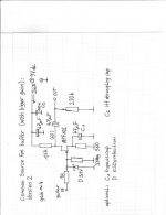
Some changes that you included in your schematic are OK (suggested by Ray), but some are not. You removed the input capacitor. This will change the DC biasing of the input FET. You also removed a capacitor between the first and the second stage of the preamp. And you also removed the resistors in the emitter follower (biasing and the temperature compensation). This will change significantly the way the preamp works (and also the power consumption). The trimmer is also not a good idea - the gain of the preamp can be easily changed by altering resistors in the first stage (to be done only once). I wouldn't recommend such changes.
Mark
- Status
- This old topic is closed. If you want to reopen this topic, contact a moderator using the "Report Post" button.
- Home
- Live Sound
- Instruments and Amps
- FET based Acoustic preamp help