Thanks for all your replies and help guys!
Minion’s circuit looks very interesting as long as I can reduce the input impedance by replacing the 2.2M resistor with a 1.0M resistor as I do need an input impedance of 1.0M. Also are the 10K resistors in the circuit there to reduce the signal and can they be removed as I would like to have a lower output impedance than 10K as my mixers line input is on the low side at 20K. Will this be OK?
Mark, you are correct, *most* piezo devices need a higher impedance input. My pickup is a bridge plate system consisting of 3 separate piezo devices in parallel. It is the K&K PureWestern system (extremely nice sounding pick up by the way!!) It is confirmed by the manufacturers (K&K Sound) to require a 1M input on the preamp. This is why this system is known not to sound good with usual preamps on the market by LR Baggs, Fishman etc which mostly have inputs in the region of 10M. The 1V output level is the abs max output under very heavy strumming etc and therefore the output will nearly always be lower (again K&K confirmed this). The output is quite high however and would probably be fine for a guitar amp input etc. I would like to have additional gain to drive the line input of my mixer without having the faders flat out and to provide a level of flexibility. A preset gain setting would be fine
Mjf, yes I too like the idea of the single ended Class A stage as I always thought the less active devices the signal goes through, the better, or the simpler the circuit the better. I just do not have the technical knowledge to see from circuits if they are tailored towards sound coloured with distortion and EQ ranges to suit electric guitars etc, and this is why I appreciate all the help you experts can give me!
Cheers
Ray
The information that you need "exactly" 1 MOhm input impedance is very confusing. Most manufacturers specify this parameter as "at least ...". In case of a piezo transducer, the more - the better. Is it confirmed by K&K Sound? If so, they should provide either a preamp, or a schematic.
Also the information that the pickup sounds not so good with preamps with higher input impedance (from other manufacturers) is also confusing. Do they try to sell you their own preamp?
If you really need it, you can change the input resistor in Minion's preamp to 1Meg and the output resistor to 1k. But remember that the output resistor, together with the next capacitor, they form a low-pass filter and if you change the resistor, it may be required to adjust the capacitor.
Mark
I use it for a bass guitar. It sounds OK but the filter is exactly as so called "Aural Enhancer" in SWR amps and it's definitely changing guitar's sound (in a nice way - lows and highs are boosted). The frequency plot of this filter is posted by me in the "Hugsley (and not Hudsley) preamp" thread - please check it.MondyT said:Mark,
You say you have built the Hudlsey’s circuit. What did it sound like?
If I do not use the pot on the output, will this drive into 20K with no problems?
Cheers
Ray
I'm also not sure what you mean by "line" input. Do you mean an input with 0.707V sensitivity or just standard instrument input?
Standard instrument input has higher input impedance. Are you trying to plug the guitar directly into a power amp?
Mark
Hi Mark
Thanks for your help my man!
K&K do in fact sell a preamp here...
K&K preamp
Which has the recommended 1M input. The output however is 10K and this seems a little high for 20K the line input on my mixer. Incidentally the mixer is a Tapco Mix-60 and I wish to drive the Line Input of this mixer. The specs for this mixer are here...
Mix series specs
I wish to drive the Line Input rather than the Mic/Instrument channels as there are only 2 Mic/Instrument channels and I need to keep these for Mics.
Before I bought the pickup system, I did a lot of sniffing around about them and found many users complaining that they could not get a good sound out of the pickup when using the usual suspect pramps by Baggs/ Fishman etc. K&K have confirmed this here...
http://www.kksound.com/help/purepreamp2.html
I could buy a preamp, but I am crazy and would get much more satisfaction using one I knocked up myself, you know the feeling!!!
Cheers
Ray
If I had a piezo pickup, I'd checked this. In my opinion it is rather the other way around; low input impedance cuts bass performance. Or you could just add a 1 MOhm resistor in parallel to the input of a preamp to lower the input impedance.MondyT said:
Anyway, I see two options: either build the Hugsley's preamp without the fillter and with output resistor changed to 1k, or build the preamp offered by Minion (also with slightly changed components).
With Minion's preamp you have more possibilities regarding gain adjustments, but the Hugsley's preamp is easier to build. The only inconvenience is that for every J-FET input transistor, you need to select resistors to adjust voltages in the preamp. The choice is yours.
Mark
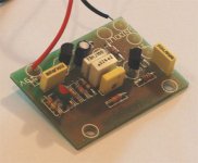
Minion said:Here is a simple Curcuit and PCB i designed (If you can call it that as it is just the basic implementaion of an opamp) that I use as active electronics in my Electric Guitar...It has 2m2 Input impedance and low output impedance
Sorry, but you are completely mistaken about the input impedance, it'a not 2.2M, it's more like 470K (actually 486K in parallel with 2.2M).
The circuit is also missing the vital supply decoupling capacitor, stick a 100uF or so directly across the power pins of the opamp.
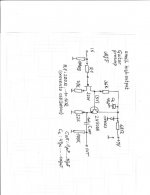
I decided to go for a modified Hugsley Guitar Preamp circuit as it seems to offer the best power consumption and it would seem that most on board buffers for Acoustic guitars, Takamine, Ovation etc all seem to have simple FET based stages, and they sound pretty good! All I needed was to remove the EQ stage from the original circuit and add a few odds and sods to make the circuit more robust as it will be used in a stomp box form (not switched however)
I have attached my circuit mod and I wondered if you experts could kindly take a look and let me know if all is OK or not.
Questions
1. Do I need the 100n cap C2 between the two stages?
2. To reduce susceptibility to RF break through, I was thinking of adding a cap of a few pF across the input jack. Is this advisable and if so how many pF would I need?
3. I upped the decoupling cap and added an inverse diode to add a little reverse polarity protection should the battery clip be reversed for a second or two. I hope I have this right as I do not want to use a series diode in the supply lead due to the volt drop?
4. I was also toying with the idea of adding a pair of back to back 5.6V zeners across the input to clamp any extraneous voltages on the input as the J201 seems quite a delicate device. Again, is this advisable?
Any thing that is glaringly wrong or if anyone has any further suggestions, they would be appreciated. Once happy, I will get hold of the bits and have a play around to see what it all sounds like.
Thanks again
Ray
Attachments
hello ray.
question3: current trough diode is round about 8,4v div. 68 ohm.......123ma. i would prefer 1n4001...........1n4007series.
may i have a question? what is the voltagegain of this amp ?(perhaps compared to the common source fet buffer)
greetings................mjf
question3: current trough diode is round about 8,4v div. 68 ohm.......123ma. i would prefer 1n4001...........1n4007series.
may i have a question? what is the voltagegain of this amp ?(perhaps compared to the common source fet buffer)
greetings................mjf
Yes, but I would increase it to at least 220n.MondyT said:I decided to go for a modified Hugsley Guitar Preamp ...
1. Do I need the 100n cap C2 between the two stages?
I'm not sure wheather it's needed. You may leave a place for a 22-33p capacitor. But the capacitor should be rather on J-FET's gate and not on the input jack.2. To reduce susceptibility to RF break through, I was thinking of adding a cap of a few pF across the input jack. Is this advisable and if so how many pF would I need?
Yes, it's OK but I would use 1N4001.3. I upped the decoupling cap and added an inverse diode to add a little reverse polarity protection should the battery clip be reversed for a second or two. I hope I have this right as I do not want to use a series diode in the supply lead due to the volt drop?
In case of internal preamp this is not needed. If you plan an external preamp, you may always solder the zeners to the input jack.4. I was also toying with the idea of adding a pair of back to back 5.6V zeners across the input to clamp any extraneous voltages on the input as the J201 seems quite a delicate device. Again, is this advisable?
You may also consider decreasing the output emiter resistor.Any thing that is glaringly wrong or if anyone has any further suggestions, they would be appreciated.
Remember that the drain resistor must be adjusted depending on the transistor's parameters.
Mark
Without the filter it's x6. This may be too much for a piezo transducer (but easy to be corrected).mjf said:What is the voltage gain of this amp?
Mark
Markus2006 said:Without the filter it's x6. This may be too much for a piezo transducer (but easy to be corrected).
I would say it has a gain of about 11 times, based on source and drain resistors.
The emitter resistor on the output is also massively too high, it's giving an output impedance higher than directly off the FET drain.
The designer of the preamp lists the gain as x6.8. I simulated the preamp in SPICE, and with the model of J201 that I have, the gain is x6.3. I'm not sure whether you can calculate the gain as ratio of the two resistorsNigel Goodwin said:I would say it has a gain of about 11 times, based on source and drain resistors.
 . For more details, I suggest reading this page: http://www.diyaudio.com/forums/showthread.php?s=&threadid=27524&perpage=25&pagenumber=4
The resistor is selected with such a high value in order to keep the power consumption at low level (0.2mA). You can decrease the resistor to 4.7k and still have the current below 1mA.The emitter resistor on the output is also massively too high, it's giving an output impedance higher than directly off the FET drain.
Mark
Markus2006 said:The designer of the preamp lists the gain as x6.8. I simulated the preamp in SPICE, and with the model of J201 that I have, the gain is x6.3. I'm not sure whether you can calculate the gain as ratio of the two resistors
You can pretty well for transistors, as long as gains are low, I never use FET's much, but wouldn't expect them to be greatly different?. Perhaps the gain of the FET is so low that the gain set by the resistors is too high?.
The resistor is selected with such a high value in order to keep the power consumption at low level (0.2mA). You can decrease the resistor to 4.7k and still have the current below 1mA.
But 100K wouldn't work - it's FAR too high to allow a low impedance output.
You are right that such a high value does not make much sense. But I checked that with a typical amp it works quite good. The problem that Ray has is that his amp has very low input impedance (which does not seem to me to be typical). Anyway, after decreasing the resistor to 4.7k, it will work for him.Nigel Goodwin said:But 100K wouldn't work - it's FAR too high to allow a low impedance output.
Mark
Markus2006 said:You are right that such a high value does not make much sense. But I checked that with a typical amp it works quite good.
If he had an amp with such a high impedance input already, he wouldn't need the preamp in the first place

The problem that Ray has is that his amp has very low input impedance (which does not seem to me to be typical). Anyway, after decreasing the resistor to 4.7k, it will work for him.
My point exactly.
Mark, Nigel and mjf, thanks very much for your help, you have been a God send here!
4.7K I feel would be fine for my mixer line input of 20K. I normally only use guitar leads of around 5 meters max and the preamp will be belt or strap mounted so the lead from the pickup into the preamp will be very short. A current consumption of 1mA or less will not be too sad either so I will go for this.
mjf, I will also obtain the parts to try your variation on the preamp and I will report back!
Should I have problems sourcing the 2N5088 transistors, could say a BC109C or similar transistor be used here or would this mean changes in the component values and problems with output impedance etc?
Cheers
Ray
- Status
- This old topic is closed. If you want to reopen this topic, contact a moderator using the "Report Post" button.
- Home
- Live Sound
- Instruments and Amps
- FET based Acoustic preamp help