That was super quick M'T,
Piezos are are not as simple creatures as one might have been lead to believe...I too though it would be easypc....no way.
Well I'will post a rather concise explanation on my "Piezo Disc Preamp" thread soon.Believe me M'T, I'am no expert..but sheer perseverance, reading a LOT & trying this damn circuit for the past 8-10 months has rearranged by brain dramatically,or the betterment of mankind I hope!?
Just curious, have you connected a preset or "pot" (150K) to adjust the input bias on the TL071?
Modifying to dual supply is quite simple really.
You'd need 2 pairs of PP3 battary clips.
Carefully strip alternate color lead from each clip.ie; red on clip1, & black on clip 2.
Looking at your circuit,
1.Remove R1
2.Connect pin +v pin (7?) to the Red lead from clip 1
3.Then connect pin 4? - v supply PIN of TL071 to the - v(black) lead of the 2nd battary (Black lead from clip 2)
3.Strip & tie together or solder -v lead from battary 1 & + lead from battary 2 together.
If your circuit is already on a breadboard/ vero board, then the +/-supply should sit on the top of the chain along with the caps & the 2 resistors.
Connect this tied pair to the common/ground on to the circuit
You shoud also add the 2 caps as explained earlier & a 22k, 33K
or 47K 1/2 W metal film resistor from each supply to the "common/ground along with these 2 caps.
I've used a DPDT mini toggle switch,which saves me the bother of removing/ reinserting the battary clips to save power.
Simply leave the "common" tied-up leads as they are & connect the 4 battary leads same colors to the switch.Presto,there you have a power on-off switch
Good luck!
Hi Teleman
Thanks for the info. Is the attached schematic correct?
Couple of things....
1. Should R2 stay as it is for a 1.0MOhm input impedance or does R2 need changing in value to 1.0MOhm?
2. As the input is in phase with the output (Non-inverting config) do you see any problems with using it for acoustic guitar amplification, will it have any effect on susceptibility to acoustic feedback in use etc?
Cheers
Ray
Attachments
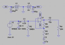
Non-invert.buffers, as I understand, have small gains & very high impedance to handle high source impedance.ie.piezo in this case.
So very high gains would make them instable.
C4 ....what is it for? I don't understand the purpose.
C1.....This value will decide your Lo freq (-3dB) cut off point
So leave it as it is for the time being..you can change to diff. values until you're satisfied with the Lo-freq.
R2..... This is still a little on the low side I'm afraid.You may not be able to drive a signal through due to the loading effect of the piezo.You could try this value with an AMP & see if it's loading or not. I am using 4M7 on mine.
R5/R3 .....I think though the ratio/values seem ok, the gain is little too high. 1+R5/R3 = 1+22k/4k7 almost= 6. But please do try this by all means.This will give you a real feel by experience.
This has to do with input bias current to the opamp as well? You'd need only about 5uA for TL071 If my memory is intact!
I remember reading somewhere that with high impedance battary powered circuits the feedback resist..should be high enough,also this reduces battary drain. I would reduce the gain by 3 with 1M/560K or 470K/ 150K but with much less current drain through the resistors.I need a second opinion here!!
R4..... this could be 20k Log pot as well,.then you'd have a volume control too!.avoid stumbling over the beer cans etc to reach for the amp every time it feeds back! he..he..
Hi Teleman
I chose the 2MegOhm resistors in the original 9v version of the circuit as I thought that Non-inverting inputs with single supplies had a circuit input impedance of 0.25 x R1+R2 = 1.0MegOhm which is precisely the input impedance that the pickup specs say is required (low for a piezo unit I know, but that is what the manufacturer recommends) This is the most important requirement of the preamp.
Secondly the circuit needs a low enough impedance to drive the 20KOhm input impedance of my mixers Line In. This is why R4 is 20K, it is supposed to be the input to the mixer for the simulation. I would not have this resistor in the final circuit. I am not going to use a volume control to preserve the low output impedance of the circuit, I will just try and keep the patch clear of beer cans!!. Do you think the non inverting output would encourage feedback?
C4, 10pF is just there as I intended to use it on the gate of the FET in the original transistor version of the preamp to hopefully give a little protection against RF break through. I have no idea if it is needed in the opamp version!!
I would ideally like a gain of around 4 as this would take my maximum input voltage of around 0.25v rms to around 1V of output, this should drive the mixer Line In nicely
I have not given up on the FET circuit yet as if I am going to think about two batteries then I may be able to bias the FET version for more gain without distortion and really this circuit is more elegant to me, it is just that I was so surprised by the quality of the sound of the opamp version, that I have to check this out as well. If the FET version can be biased with 18v to get minimum distortion then it will be down to listening tests to determine the final circuit
Cheers
Ray
MondyT,
Well,of course you should use the 2M res.as long as it is high enough as to not induce loading effect.It will only show when you actually plug the pre into an amp!
I forgot,what pick-up is it?
To your second statement,it's not correct really,since all inverting & non inverting opamps have a very low out put resistance.(That's the whole point of using opamps!) not even in the Kohm range.So they wont load any inputs & will definitely NOT load the 20k pot! But it's a normal practice to include some "load resistance on the o/p, 'cause these also give some protection to the opamps from returning back voltages/currents destroying it.
Outputs,whether from a non invert or invert opamp don't feed back,it depends mostly on the overall gain of the circuit itself. inadequate earthing, improper cabling,shielding,impedence mismatch can also cause feedback.
C4. as I explained earlier ...sorry I don't understand of it's purpose at all.(you could perhaps ask an expert)
I then presume that you intend working on line level signals?
I can't really comment since don't know much about FET's , but.arn't these prone to severe temperature drift,which can affect it's preformance?
Oh,did you know that on blind test(s) more than 85% percent of musicians couldn't tell a FET based sound from an Opamp based one!!(read it somewhere recently)
Some food for thought hey!
cheers
- Status
- This old topic is closed. If you want to reopen this topic, contact a moderator using the "Report Post" button.