For some reason, I only ordered two .56 resistors. Placed an order for other few parts I was short on...no pun intended. Just glad the Jensen transformers survived.
Sure, we are still friends. He insists on paying me for the parts, even though it was just a few dollars. Friend gave me an entire music server, of which I will using parts from for a long time. Linear computer power supplies, SATA noise silencers, aluminum chassis, etc. How can I ask for parts money?
I blew up Scott's (SRMcGee) F5 Turbo mono block trying to adjust the 2nd harmonic a little while back. We fix it and moved on. We help each other out. Something we break stuff. It happens. As Scott said, no one got killed this time. I still shake my head with embarrassment when I think about it, but we move on.
Sure, we are still friends. He insists on paying me for the parts, even though it was just a few dollars. Friend gave me an entire music server, of which I will using parts from for a long time. Linear computer power supplies, SATA noise silencers, aluminum chassis, etc. How can I ask for parts money?
I blew up Scott's (SRMcGee) F5 Turbo mono block trying to adjust the 2nd harmonic a little while back. We fix it and moved on. We help each other out. Something we break stuff. It happens. As Scott said, no one got killed this time.
I still shake my head with embarrassment when I think about it, but we move on. I have decided to try an build an F6 & F6 ish amps but have some wonderings about it:
First is about the input stage. I have a low source impedance of 100 ohm so I will skip the buffer, which is nice as the JFETs are hard to get anyway.
I do, however, have a balanced source so I'd love to use balanced input to the transformer if possible. The issue lies in that I'm not sure how I should go about it to integrate it with the feedback loop.
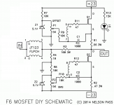
Let us start with the normal unbuffered F6. Nothing fancy here.
If it is too messy to use balanced input and keep the smart feedback of the F6 I might just give up and use single ended but it would be nice to know that options I have =)
First is about the input stage. I have a low source impedance of 100 ohm so I will skip the buffer, which is nice as the JFETs are hard to get anyway.
I do, however, have a balanced source so I'd love to use balanced input to the transformer if possible. The issue lies in that I'm not sure how I should go about it to integrate it with the feedback loop.
Let us start with the normal unbuffered F6. Nothing fancy here.
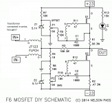
- I believe I could series connect the transformers as in the second image. Should work but this should loose some gain right?
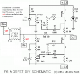
- Another option I think is to parallel connect the transformer but add a negative input at the other side. The question here is about the series resistors though. If I'm not mistaken I want them high as to not mess with the feedback loop but if I remember correctly they become my input impedance so I don't want to set them too high.
If it is too messy to use balanced input and keep the smart feedback of the F6 I might just give up and use single ended but it would be nice to know that options I have =)
Attachments
It's messy.
Thanks for answering, single ended input or less gain it is.
There is to fun to be had next weekend though, assuming my transformers and boards from the store get here in time =)
I have some F6 configurations I want to try out, one standard with IRFP240 and then some others with different output devices.
I got too curious and bought a lot of IXFH220N06T3. I kept eyballing the massive transconductance combined with the linear capacitance and the pentodyness in the vgs curves, should be fun toying with them in the F6 setup. They also seem to perform well at lower voltages so I will have to try cascoding them with R085s when I'm at it.
OilBoil
You might check out buzzforb's Funny ^6
http://www.diyaudio.com/forums/pass-labs/233101-funny-6-a.html
Really nice balanced amp - in my top 2 diy list
You might check out buzzforb's Funny ^6
http://www.diyaudio.com/forums/pass-labs/233101-funny-6-a.html
Really nice balanced amp - in my top 2 diy list
Cool, might be a project in the future. For now I just want to keep it simple and nice =)
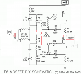
One issue though is that I do not have dual 24V supplies but I do have a single 48V. So My proposed solution to use a single supply is:
I'm pretty sure my DACs (Hypex DLCP) do not have DC on the output so I might omit the input cap. Though on second thought I'm not sure it would matter even if it did as it is a transformer.
Attachments
Last edited:
you can use so called Quad trick ,for making bipolar supply from unipolar
look at Quad 606 schematic
Interesting, that schematic helped me find the virtual ground for power amps thread.
I have now tried an F6 with IXFH220N06T3, IRFP240 and IXFK140N20P (pretty much the BAF2015 Schade amps IXFN140N20P but in a cheaper plastic package)
No resistor changes apart from having it cap coupled as I only have a single supply and a resistor from bottom of R1 to bottom of P1 so that Q1 biases up nicely. I put 10k but in hindsight I believe you could simply short it as I the feedback loop was separate on my amp.
The IXFH220N06T3 didn't behave nicely at all. They say 440W @ 25c but in my experiments they are extremely fragile. When testing it in the F6 they broke when conducting 24V @ 1.4A. I've had other experimental amps and they broke in those setups too. The only kinda successful (as in not breaking) build I had was when I ran them at 5V @ 1.5A cascoded by a R085 running at 19V @ 1.5A but then I didn't measure even close to the monstrous transconductance I was hoping for. In a single ended setup with no degen I got ~ 35x gain where my R100 in the same setup got ~ 75x. So I have abandoned the IXFH220N06T3 at least for now.
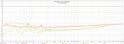
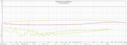
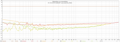
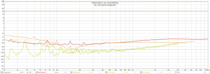
So the IXFH220N06T3 is out, how about the others but with actual measurements? So here are some!
I believe the low frequency hiccups from the transformer is because my testing source is not... ideal. I had hoped that the line outs of my external sound card had sub 100 ohm output impedance but well... that was not to be It had over 10k so without a buffer it didn't work so well. I did get something workable when using the headphone output which sat at 50 ohms but those hiccups appeared. In the long run I'll do tests with my actual source (Hypex DLCP) which should perform better but these should do for now.
The IRFP240 seems to be a pretty good device in the F6. The beast mosfet derails at higher output which if I'd guess has something to do with that the capacitance falls apart when having less than 15-20V over the fets. So would probably need some extra care to work well but as the IRFP240 works perfectly in the F6 why bother?
No resistor changes apart from having it cap coupled as I only have a single supply and a resistor from bottom of R1 to bottom of P1 so that Q1 biases up nicely. I put 10k but in hindsight I believe you could simply short it as I the feedback loop was separate on my amp.
The IXFH220N06T3 didn't behave nicely at all. They say 440W @ 25c but in my experiments they are extremely fragile. When testing it in the F6 they broke when conducting 24V @ 1.4A. I've had other experimental amps and they broke in those setups too. The only kinda successful (as in not breaking) build I had was when I ran them at 5V @ 1.5A cascoded by a R085 running at 19V @ 1.5A but then I didn't measure even close to the monstrous transconductance I was hoping for. In a single ended setup with no degen I got ~ 35x gain where my R100 in the same setup got ~ 75x. So I have abandoned the IXFH220N06T3 at least for now.
So the IXFH220N06T3 is out, how about the others but with actual measurements? So here are some!
I believe the low frequency hiccups from the transformer is because my testing source is not... ideal. I had hoped that the line outs of my external sound card had sub 100 ohm output impedance but well... that was not to be
It had over 10k so without a buffer it didn't work so well. I did get something workable when using the headphone output which sat at 50 ohms but those hiccups appeared. In the long run I'll do tests with my actual source (Hypex DLCP) which should perform better but these should do for now.The IRFP240 seems to be a pretty good device in the F6. The beast mosfet derails at higher output which if I'd guess has something to do with that the capacitance falls apart when having less than 15-20V over the fets. So would probably need some extra care to work well but as the IRFP240 works perfectly in the F6 why bother?
Attachments
F6 Power supply current per rail question
I'm constructing an F6. I have a nice big power transformer that has four 24volt (unloaded) secondaries. This transformer had been originally destined for a Pass A40 project which I bought in an unfinished state. I realize that the secondary voltage is too high for the typical F6 amplifier so I bought a quad of Hammond 159ZC chokes to use in a semi-choke input power supply topology.
Straight choke input yields only 19v into the amp's PS capacitors. I find that with a 1.5 A load I can get the supply to 23 volts with a few hundred uF ahead of the choke. My question is, if I want to ultimately bias my F6 to 1.5 amps of current what should I expect on each of the bipolar power supply rails? What would I see in static current on each of the plus and minus supplies?
In this amp I will have four bridge rectifiers providing four discrete supplies.
You have missed the point. I am already creating a live power supply into an active 1.5 A load. What I don't understand is in a Pass F6, if you set the bias at 1.5 amps, what kind of current load would we expect on THE Positive SUPPLY, and then, on THE Negative SUPPLY in real world operation.try Duncan's PSUD
By the way. Duncan's PSUD has many faults including not being able to model with inductors less than 1 mH. The default values for power transformer specs seem far from reality and I don't find any wisdom anywhere on tweaking the defaults into real world results. Also the default capacitor esr values seem way off and again, nothing to reference for actual parts. Why bother with PSUD if you can't actually model a real circuit with accuracy? It is a toy.
YouAgain,You have missed the point. I am already creating a live power supply into an active 1.5 A load. What I don't understand is in a Pass F6, if you set the bias at 1.5 amps, what kind of current load would we expect on THE Positive SUPPLY, and then, on THE Negative SUPPLY in real world operation.
By the way. Duncan's PSUD has many faults including not being able to model with inductors less than 1 mH. The default values for power transformer specs seem far from reality and I don't find any wisdom anywhere on tweaking the defaults into real world results. Also the default capacitor esr values seem way off and again, nothing to reference for actual parts. Why bother with PSUD if you can't actually model a real circuit with accuracy? It is a toy.
1.5A is the quiescent current, which means it theoretically will swing to +3A before it leaves class A to class AB. But due to the square law nature of the FETs, if u have small or no degenerative resistor, it will leave class A any where from 3.2A to 4A depending on your device. I would say plan for peak current of 5A
Sent from my XT1575 using Tapatalk
......It is a toy.
wrong
in my hands - paintbrush is a toy .....
numerous examples that ppl are using PSUD with accurate results
anyway , instead of learning how to use PSUD (also learning necessary basics of electronic) , go with simple logic :
Papa is using 18Vac secondaries , resulting in rails approx. of 22V5dc , with usual FW Iq range
you have 6Vac more in secs , so you'll have 6V more in DC realm - around 28V5
so - go with L input filter , then add capacitance in front of L to achieve desired DC rails , ending with something known as tuned choke input filter supply
with some luck , you'll stay out of LC resonance area
- Home
- Amplifiers
- Pass Labs
- F6 Amplifier