I would certainly not lose sleep over some added inductance between a 6” wire and a 2” wire…
You might, if that added inductance or noise pickup causes the amp to self-destruct.
@Zen Mod Thank you sir, I do appreciate it.
The number of cool bikes that come out of such a small county is ridiculous. Must be something in the water...
No thank you. I spent more hours "admiring" the underside of my single Alfa Romeo that I've spent driving the 30+ Hondas I've owned.
Italians make beautiful things, for sure, just don't ask them to have reliable moving parts.

All roads are leading to Gianluca's and Moto Guzzi Capital
anyhow - if one can slab them ( transistors) ditto on pcb with fat traces, keeping all nodes at minimum (inter)distances, it is simpler for production (allowing repetitive quality and performances) , usually better in exploitation (or should I say - use)
proper PtP arrangement is, well, proper - but even if possible to get to slightly higher level of construction quality in some cases, usually more labor intensive and - if really done to exploit everything** what PtP is giving as benefit - proper nightmare for service
** 3D arrangement of circuit, rather than more 2D oriented with pcb as base
anyhow - if you're wrestling with just one pair of outputs - go with your heart, do what you like
if more output pairs are involved ......... better to stay with pcb ........ or resort to "rails" (you can also call them "Busses") principle, but then - again - that's no "3 wires to each transistor"
So for prototypes we're better off mounting the output transistors off the driving PCB. That makes swapping output transistors and mechanically fitting the parts much easier. The trade is complexity vs upgradeability.
For production, where the design is complete and finalized as part of the preproduction R&D, mounting the transistor to the PCB directly, and then mounting the board to the heatsink is a lot more economical.
Now, here's another one... packaging the heat sink is a PITA. How about mounting the output transistors onto a simple metal slab and then using a heat pipe to transfer the heat to an external heat sink ( or radiator ). That would solve the problem of how to package the likes of an Aleph 0...
Mind you.... there's still another point... the F5 is designed so the PCB is mounted onto the heatsink... that thermistor has to touch the board. From experience, if you have UPS ship a DIY F5, when receiving it, make sure to verify that the thermistor is really touching the heat sink before turning it on.
It might look like it is... otherwise you will get... smoke.
Last edited:
Just curious, would the addition of gate stoppers be advisable with ~3" flying leads?
Instability depends on various parameters that can vary. Why risk problems?
Take a look at this.
Attachments
Mind you
remind you - many of original FW F5 were sold all over the world; same NTC needing to stay in same spot, while flying in all possible ways
it's easy - just make an amp that good as Papa does it, all problems solved
what's best way to catch a Wabbit ?
put some salt on his tail
we can talk all day about various types of Wabbits and various types of salt, but in the end everything falls to same
^ I did write DIY amp.... things happen.
Also, commercial amps are packaged a lot better. UPS can destroy things, but hopefully the commercial products are better insulated against shocks.
I had a pair of small speaker shipped to me by a family member. When I got the box, it literally came in a UPS open box "basket" with the parts inside. They broke the woofer baskets! I can't figure out how they did that? Dropped it from 50 feet?
I've had heatsinks bent, boxes ripped, etc, etc... how UPS (and FedEx ) stay in business with that quality is beyond me.
I once had a 45" flat panel shipped to me... they'd driven something like a forklift into it.... the damn thing said FRAGILE and they still delivered it to me. with a gaping hole in it... they dropped it at my doorstep without getting my signature, as required. Perhaps UPS thought I wouldn't notice the hole in the box.
Monkeys.
I've been thinking of making some custom foam shipping boxes for my DIY amps. I keep all the boxes for my commercial products.
https://www.alpharfsystems.com/?ec_...tom-foam-kit-amplifier-inner-box-for-shipping
Last edited:
Did that on the dual amp/dual mono F6 on one amp. Boards are bridged.something like 12 gauge? And keep them in parallel
Thank you. I'll give that a close read later tonight.Instability depends on various parameters that can vary. Why risk problems?
Take a look at this.
Nice, looks like it's going to work! Spacing of bolt holes for the little seat is 100mm, based on Modushop perforated plate. Since you're re-using a used amp chassis you don't really need to mount the seat using hardware. If you tighten the straps down tight, the force squeezing it down should hold it in place just fine (saves drilling two holes). Just make sure the strap holes you mark and drill are slightly "inside" the edges of the transformer so they can really grab the transformer to the maximum extent possible.
Easter Egg: I've got 5 more kits up to give away at this time if interested party sends me a shipping label. 1 per person please. I'll toss in some other 3D printed goodies for fun. The mount "kit" I'm offering for free has the 3D printed seat, pipe strap with rubber guard, and all hardware needed to mount it. (designed for Antek 300 & 400 series transformers, but may work on others with same/similar diameter).
https://www.diyaudio.com/community/threads/transformer-chassis-seat-antek-300-400.410463/
Last edited:
I read the entire thread yesterday, in the beginning there were a few questions to what extend the F5M changes could also be applied to other F5 versions, but no real answer.
I recently finished a balanced F5T V3 (as per the V3 schematics in the article but without the diodes, no P3, paralleled input Jfets, 22V rails). I like the amplifier, but it doesn't have the same mid-range transparency and overall "niceness" of my trusted balanced F4's, so I'm willing to experiment a bit.
One possibility would be to add P3 and see what that changes, but I don't have an analyzer. So, to what extend is it viable to try out some of the F5M changes in the F5T?
I assume the most relevant are R3/4/5 in F5M equivalent to R3/4/7/8/9/10 in the F5T V3 schematics.
Why I'm asking, in the F5T article Nelson is suggesting the Feedback loop impedance needs to be decreased when paralleling Jfets (which I do) and the F5M changes will result in the opposite. Also, is the change of R1 relevant?
Many Thanks
Sven
I’ve constructed a F5m in a smaller chassis: a Niles SI-275 home theater amp with a decent (but internal) heatsink for a class A/B amp, and a 17”x4”x13” overall size. It has about 70% of the heatsink of the smallest chassis Nelson commented on in his write up. I knew I would need to have some active cooling to bias it at 1 amp or higher, and I have the fans ready to go once I more thoroughly test it at lower bias. As I was using a smaller chassis and not intending to run at the highest bias this amp is capable of, I chose to fit it with the smaller Antek AS-2218 transformer.
Original chassis

Empty chassis, but I left some original harness in. Heatsink at left, upended, with mock up of F5m channel PCBs sitting on it.

The build went reasonably well over the past few days. This is my first chassis-based build, and I followed many of the clues provided by 6L6’s photos in the F5m threads, as well as some of his other build threads. The only unanticipated issues I ran into were not being able to put as much space as I’d have liked to between the AC and DC circuits, and some awkward cable routing compared to what can be done in a more spacious chassis.
Finished chassis

In terms of “options”, I did mount the channel PCBs by their Mosfets (I did not want to drill and tap holes for the boards), I added the purple shield wire from the Antek to the star ground to get what shielding I could from it, I used a Murata ceramic X1-Y2 10000pF safety cap across Hot and Neutral, and installed a 2A slo-blow mains fuse. I reused the power switch, RCA jacks, and speaker terminals from the Niles. I used the transistor pads from the kit because with them I got O.L on MΩ scale between any legs on the Mosfets and the bare metal (screw hole) of the anodized heat sinks.
I completed the build this morning, and in the last few hours have been seeing how it behaves in biasing without any fan assist. In case anyone else is contemplating building in an undersized chassis, I’ll describe what I experienced.
The amp wakes up at midpoint on the pots, and after verifying rail voltage, I set it at about 290mV bias (about 0.6A) and could feel the heat start to come up in the sinks. DC offset was easy enough to dial in with the dance of the two pots, although “touchy” would be a generous description. I let an hour or so pass without making any further adjustments as it warmed up with the cover off. Bias stabilized by 45 min at about 435mV (0.925A) and the heatsinks stabilized at 53°C. Room was 18°C. I was surprised I could get the bias that high without a fan.
I then placed the cover on, and it was a different story. By 25 min with the cover on, bias had risen to about 455mV (0.97A), and the sinks were at 59°C. Over the next hour or so, I adjusted the bias downward a couple of times, giving it time to settle, but I needed to get it down to about 310mV (0.66A) to stabilize at 53°C.
I’ll see where I can go with fans in the coming days, but I needed to listen to this thing first, especially because I was concerned that the closeness of AC voltages to channel PCBs might give me a noise problem. I placed it in a system with DCM Time Windows (low 90s sensitivity) and could hear a faint buzz with my ear at the speaker. For comparison, I could not hear anything from the ACA Mini or the ACA Redux I had built. I don’t know if the difference is due to how I laid out my F5m, but the noise level isn’t perceptible to me by a foot away and is something I will have no problem living with.
I’ve only been listening for about an hour and in a low-bias condition (0.66A), but it sounds lovely and very detailed. I listened to some Richard Stoltzman clarinet cuts, and the clarity and beauty sent me right to where I love to be.
I plan to experiment with running with fans and at higher bias over the next week or so and will update here with my experiences when I do. Until then, many thanks to Nelson for his generosity and his brilliance, both of which were necessary to allow a piker like me to build this amp.
.
Original chassis
Empty chassis, but I left some original harness in. Heatsink at left, upended, with mock up of F5m channel PCBs sitting on it.
The build went reasonably well over the past few days. This is my first chassis-based build, and I followed many of the clues provided by 6L6’s photos in the F5m threads, as well as some of his other build threads. The only unanticipated issues I ran into were not being able to put as much space as I’d have liked to between the AC and DC circuits, and some awkward cable routing compared to what can be done in a more spacious chassis.
Finished chassis
In terms of “options”, I did mount the channel PCBs by their Mosfets (I did not want to drill and tap holes for the boards), I added the purple shield wire from the Antek to the star ground to get what shielding I could from it, I used a Murata ceramic X1-Y2 10000pF safety cap across Hot and Neutral, and installed a 2A slo-blow mains fuse. I reused the power switch, RCA jacks, and speaker terminals from the Niles. I used the transistor pads from the kit because with them I got O.L on MΩ scale between any legs on the Mosfets and the bare metal (screw hole) of the anodized heat sinks.
I completed the build this morning, and in the last few hours have been seeing how it behaves in biasing without any fan assist. In case anyone else is contemplating building in an undersized chassis, I’ll describe what I experienced.
The amp wakes up at midpoint on the pots, and after verifying rail voltage, I set it at about 290mV bias (about 0.6A) and could feel the heat start to come up in the sinks. DC offset was easy enough to dial in with the dance of the two pots, although “touchy” would be a generous description. I let an hour or so pass without making any further adjustments as it warmed up with the cover off. Bias stabilized by 45 min at about 435mV (0.925A) and the heatsinks stabilized at 53°C. Room was 18°C. I was surprised I could get the bias that high without a fan.
I then placed the cover on, and it was a different story. By 25 min with the cover on, bias had risen to about 455mV (0.97A), and the sinks were at 59°C. Over the next hour or so, I adjusted the bias downward a couple of times, giving it time to settle, but I needed to get it down to about 310mV (0.66A) to stabilize at 53°C.
I’ll see where I can go with fans in the coming days, but I needed to listen to this thing first, especially because I was concerned that the closeness of AC voltages to channel PCBs might give me a noise problem. I placed it in a system with DCM Time Windows (low 90s sensitivity) and could hear a faint buzz with my ear at the speaker. For comparison, I could not hear anything from the ACA Mini or the ACA Redux I had built. I don’t know if the difference is due to how I laid out my F5m, but the noise level isn’t perceptible to me by a foot away and is something I will have no problem living with.
I’ve only been listening for about an hour and in a low-bias condition (0.66A), but it sounds lovely and very detailed. I listened to some Richard Stoltzman clarinet cuts, and the clarity and beauty sent me right to where I love to be.
I plan to experiment with running with fans and at higher bias over the next week or so and will update here with my experiences when I do. Until then, many thanks to Nelson for his generosity and his brilliance, both of which were necessary to allow a piker like me to build this amp.
.
Are you planning on temperature fan speed control?I’ll see where I can go with fans in the coming days,
@northpaw
That chassis is not very tall, so you may be able to squeeze a couple of 80mm Noctua fans on the back panel pulling hot air out of the chassis. If there is any space above the sinks, you may be able to block off the vent holes on the top panel so all air goes in under the sinks and out the back…
Or just have a ZM ‘babysitter‘ under the whole amp.
Nice, clean build, regardless. Good luck!
Attachments
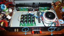
northpaw, Some suggestions for noise abatement:
1. Try rotating the power transformer to see if that changes the noise level. I suggest approximately 90 degrees counterclockwise may give the lowest noise level.
2. Try locating the bridge rectifier and transformer secondary connections on the terminal block farther away from the amplifier PCBs.
3. Try rotating the power supply board so that the DC input side is farther away from the amplifier PCBs. Try different orientations.
No, not as in an active controller, based on a sensor. The paired set of fans I have (I said a little about them here) come with an integrated manual speed control. My hope is that a minor assist to the natural upward convective flow through the heatsink fins will provide all I need. However, I can see the potential advantage of a temp-based speed control in doing a better job of regulation when dealing with a wide range of ambient temperatures (e.g., seasonal).Are you planning on temperature fan speed control?
Thanks for the comments. Yeah, there is no vertical room inside the chassis; it's pretty much floor-to-ceiling heatsink, all 3" of it. As far as the back panel, neither it or the bottom panel (save the opening right under the heatsinks) have any openings in them, and it would be a metalwork project beyond my skills to cut out such a hole.That chassis is not very tall, so you may be able to squeeze a couple of 80mm Noctua fans on the back panel
Generally, I'm inclined to try to work with the natural flow of things rather than redirect them. I'm pretty hopeful that aiding the natural upward convective flow by placing two 80mm fans directly over the PCB boards, exhausting upward, will be more than adequate to get me to 1A or so. The big bottom opening will be my friend here. The little bit of training I got in heat transport and diffusion in grad school (error function solutions and all that) gave me an appreciation for effectiveness of maintaining a surface at ambient temperature in a diffusion couple. We'll see.
Ben Mah - Thanks for sharing your insights. I may be able to rotate the transformer a bit without disturbing the wiring too much. I went back and forth on its orientation and in the location of the barrier strip and rectifier. I was constrained by the length of transformer wires (preferred not to have to splice extensions on them), and was also thinking about potential interference with the speaker-out wiring along the back, although in retrospect I shouldn't have worried as much about those higher-level signals. The barrier strip and PS PCB are only temporarily fixed in place by industrial-grade double-sided foam tape, and the side of the rectifier to the strip by the same (and by a bit of "stiction" on its bottom from the thin smear of thermal compound I placed there), so repositioning won't be difficult, but at the cost of redoing a fair bit of the wiring.
Thanks again for these suggestions. Working on this project has given me a much greater appreciation for all the thought that goes into smart design. You know it when you see it, but that hasn't made it easy to achieve when you find yourself in the driver's seat.
Thanks again for these suggestions. Working on this project has given me a much greater appreciation for all the thought that goes into smart design. You know it when you see it, but that hasn't made it easy to achieve when you find yourself in the driver's seat.
- Home
- Amplifiers
- Pass Labs
- F5m kit