
50MM x 90MMamplifier PCB size
Excuse my ignorance on this....
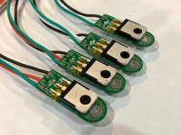
Is there a reason why these amps in DIY have the output transistors mounted on the PCB?
Why not mount the output transistors on the heat sink and then run a short set of wires from the PCB to the transistor? Is it easier to solder to the PCB directly?
How about a small board to which the transistor is soldered and then it has a clip on connector for a ribbon, or just thick wires, to another connector on the main PCB? The connection between the transistors and main PCB would then be mechanical and rather easy to swap. You could have transistor/heatsink assemblies that could easily be swapped ( allowing for rebiasing as needed ).
Is there a reason
I bet you didn't even think of marrying through proxy .......

That's similar to matching a transmission line impedance at both ends.
https://resources.system-analysis.c...ding-impedance-matching-in-transmission-lines
https://resources.system-analysis.c...ding-impedance-matching-in-transmission-lines
Unnecessary parasitic inductance is usually bad.
But you could use large wires to connect... something like 12 gauge? And keep them in parallel, not twisted.
I bet you didn't even think of marrying through proxy .......
No, we met at a punk, New Wave, club.
Frank Zappa was sooo right.
Love your nails
You must be a Libra
Aaah, the good old days, before AIDS, Rap
But you could use large wires to connect... something like 12 gauge? And keep them in parallel, not twisted.
Thicker wires won't be as effective as shorter lengths to reduce inductance, and are more difficult to work with.
The inductance is nearly proportional to length, so shorter is better.
Twisting actually does reduce the loop inductance, although twisting should only be done with the base/gate
and the emitter/source wires. You don't want to couple noise into that pair of terminals from other nodes.
Novice power electronics students have often made that mistake, and the consequences are not pretty.
Love your nails
You must be a Libra
All roads are leading to Gianluca's and Moto Guzzi Capital
anyhow - if one can slab them ( transistors) ditto on pcb with fat traces, keeping all nodes at minimum (inter)distances, it is simpler for production (allowing repetitive quality and performances) , usually better in exploitation (or should I say - use)
proper PtP arrangement is, well, proper - but even if possible to get to slightly higher level of construction quality in some cases, usually more labor intensive and - if really done to exploit everything** what PtP is giving as benefit - proper nightmare for service
** 3D arrangement of circuit, rather than more 2D oriented with pcb as base
anyhow - if you're wrestling with just one pair of outputs - go with your heart, do what you like
if more output pairs are involved ......... better to stay with pcb ........ or resort to "rails" (you can also call them "Busses") principle, but then - again - that's no "3 wires to each transistor"
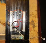
Found this old pic. Roger Sander's "No Compromise" ESL's hiding there on the side...or resort to "rails" (you can also call them "Busses") principle, but then - again - that's no "3 wires to each transistor"
Attachments
- Home
- Amplifiers
- Pass Labs
- F5m kit