Quiet Cooling Fans-
I found this site with a bunch of quiet cooling options and parts. Very interesting.
Quiet Computer Fans
Forced cooling is going to solve the rejected heat problem for lots of people. Might as well start thinking about it now.")
Regarding using fans, would it be for extra ventilation for the inside of the enclosure or directly on the heatsinks?
I might add a fan for the inside of the case on my v2 build to keep the inside temp low. Maybe with a heat sensor so it only starts spinning when the temperature reaches or passes a certain value, shouln't be too hard to do.
The F5 Turbo power supply avoids an extra rectifier voltage drop vs the F5 supply. Bob Cordell's book "Designing Audio Power Amplifiers" describes the two rectifier variations, indicating potential problems with the Turbo power supply topology if positive and negative rail currents are different. In that situation, dc current flows through the transformer winding, which is to be avoided.
How about use the dual rectifier and a transformer with a couple more volts?
Regarding using fans, would it be for extra ventilation for the inside of the enclosure or directly on the heatsinks?
I might add a fan for the inside of the case on my v2 build to keep the inside temp low. Maybe with a heat sensor so it only starts spinning when the temperature reaches or passes a certain value, shouln't be too hard to do.
Plan on the same .......
Hello
Can someone tell me the turbo version is to achieve better sound or higher power or both.
If only for higher power I really do not need that.
I do not find Mr. Pass post or comments on these amp.
Can someone help me to find it so I can read about.
I have several Pass DIY amps, Aleph2, AX, FJ, F5..... Thank you Mr Pass
Greetings Gabor
Hello
Can someone tell me the turbo version is to achieve better sound or higher power or both.
If only for higher power I really do not need that.
I do not find Mr. Pass post or comments on these amp.
Can someone help me to find it so I can read about.
I have several Pass DIY amps, Aleph2, AX, FJ, F5..... Thank you Mr Pass
Greetings Gabor
Quoted from the F5-T manual.
"Subjectively this is a little different than the original. The lesser amount of
feedback and larger output stage makes it seem a little more authoritative
while at the same time a little more relaxed. "
Regarding using fans, would it be for extra ventilation for the inside of the enclosure or directly on the heatsinks?
I might add a fan for the inside of the case on my v2 build to keep the inside temp low. Maybe with a heat sensor so it only starts spinning when the temperature reaches or passes a certain value, shouln't be too hard to do.
All you need is a spare thermistor a spare mosfet and a spare pot, Bits and pieces you probably have alredy.
Sorry at work at present look on MY F5 tread sch is there
If you use 2 12 V fan in series LM317 is redundant
UKToecutter:
I have some concerns about noise in the multi-board F5 Turbo. The (potential) problem is the the output boards have a voltage gain of between 8 and 16 into a 4 ohm load. The Turbo kicks in, the gain gets even higher. The voltage gain is calculated as follows:
Vgain = Rload * N-fets * 1/(Rsource + 1/Gm)
where Rsource = .5 ohm, Gm approx 2S.
The problem is that any voltage difference between the power rails of the output boards and the input boards due to noise will be amplified by the output stage. The Burning Amp v2.0 doesn't have voltage gain, since the MOSFET outputs are voltage followers.
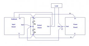
This means that extra care is required to avoid AC voltage drops. The power rail wiring must be done carefully. Capacitors C2 and C2 probably should be eliminated or on the output boards rather than the input board to eliminate ripple and noise currents running through the rail wiring to the input boards. I suggest something like the following sketch:
I have some concerns about noise in the multi-board F5 Turbo. The (potential) problem is the the output boards have a voltage gain of between 8 and 16 into a 4 ohm load. The Turbo kicks in, the gain gets even higher. The voltage gain is calculated as follows:
Vgain = Rload * N-fets * 1/(Rsource + 1/Gm)
where Rsource = .5 ohm, Gm approx 2S.
The problem is that any voltage difference between the power rails of the output boards and the input boards due to noise will be amplified by the output stage. The Burning Amp v2.0 doesn't have voltage gain, since the MOSFET outputs are voltage followers.
This means that extra care is required to avoid AC voltage drops. The power rail wiring must be done carefully. Capacitors C2 and C2 probably should be eliminated or on the output boards rather than the input board to eliminate ripple and noise currents running through the rail wiring to the input boards. I suggest something like the following sketch:
Attachments
Should be fine. You should only need about 1 volt extra.How about use the dual rectifier and a transformer with a couple more volts?
Regarding using fans, would it be for extra ventilation for the inside of the enclosure or directly on the heatsinks?
That would be completely dependent on your heatsinks. If they are undersized, (or made for forced cooling) they will need a fan.
As voltage gain increases when turbo kicks in due to appearent diminushing Rs isn't that producing some kind of expansion of the dynamic?
Last edited:
As voltage gain increases when turbo kicks in due to appearent diminushing Rs isn't that producing some kind of expansion of the dynamic?
No, the feedback loop takes care of that. With turbo "kicked-in" the open-loop gain increases, and hence the amount of negative feedback also increases.
UKToecutter:
I have some concerns about noise in the multi-board F5 Turbo. The (potential) problem is the the output boards have a voltage gain of between 8 and 16 into a 4 ohm load. The Turbo kicks in, the gain gets even higher. The voltage gain is calculated as follows:
Vgain = Rload * N-fets * 1/(Rsource + 1/Gm)
where Rsource = .5 ohm, Gm approx 2S.
The problem is that any voltage difference between the power rails of the output boards and the input boards due to noise will be amplified by the output stage. The Burning Amp v2.0 doesn't have voltage gain, since the MOSFET outputs are voltage followers.
This means that extra care is required to avoid AC voltage drops. The power rail wiring must be done carefully. Capacitors C2 and C2 probably should be eliminated or on the output boards rather than the input board to eliminate ripple and noise currents running through the rail wiring to the input boards. I suggest something like the following sketch:
Yes,
I see your point, however, I would also imagine that any ripple would be a greater problem on the input stage.
It's not a big deal to add some cap positions on the ouput boards although it will mean running a ground connection that wasn't previously required.
Hello UKToecutter
Would you please be so kind put me to the list for a stereo V3 set with one PS board.
I did tried but I couldn't do.
Greetings Gabor
Gabor
for a stereo V3 you'll need 2 input boards, 4 output boards and 2 PSU's
- Status
- This old topic is closed. If you want to reopen this topic, contact a moderator using the "Report Post" button.
- Home
- Amplifiers
- Pass Labs
- F5 Turbo Circuit Boards