Ihquam, sure.
Here we go.
Single output board (for those who want the ultimate flexibility on heatsink layout)
Board size 35mm x 50mm
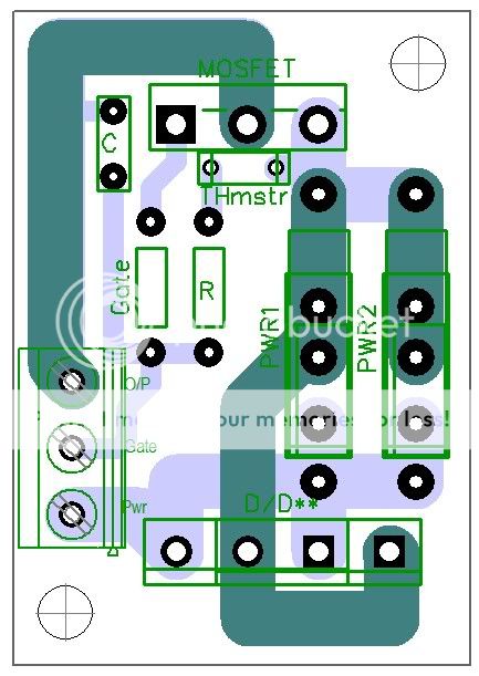
Input Stage for V3 (or V2)
Board size 70mm x 70mm
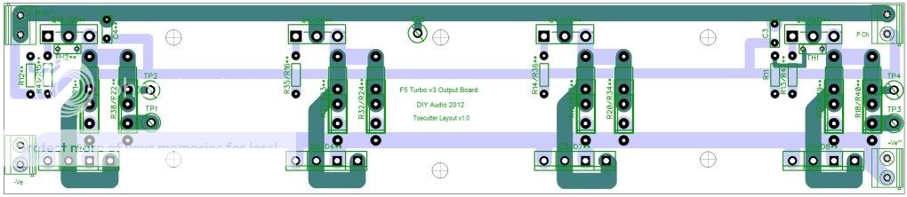
V3 Output Board
Board Size 236mm x 50mm
MOSFET spacing 65mm between centres
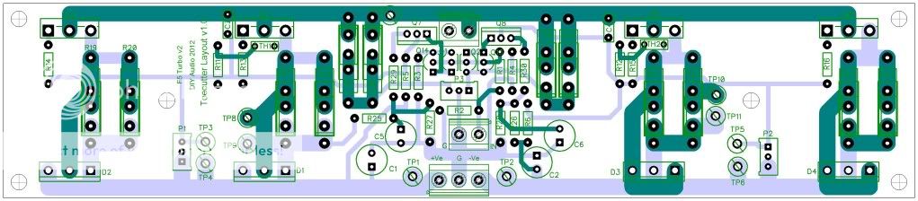
V2 Combo Board
Board size 234mm x 50mm
MOSFET Spacing 50mm - 50mm - centre - 50mm 50mm
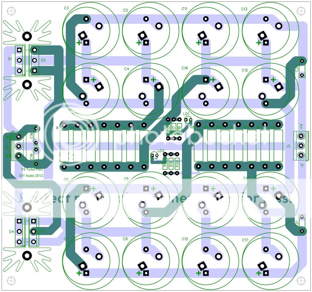
Power Supply Board
Board size 162.5mm x 152mm
Hope this answers your question.
Andy
Here we go.
Single output board (for those who want the ultimate flexibility on heatsink layout)
Board size 35mm x 50mm
Input Stage for V3 (or V2)
Board size 70mm x 70mm
An externally hosted image should be here but it was not working when we last tested it.
V3 Output Board
Board Size 236mm x 50mm
MOSFET spacing 65mm between centres
V2 Combo Board
Board size 234mm x 50mm
MOSFET Spacing 50mm - 50mm - centre - 50mm 50mm
Power Supply Board
Board size 162.5mm x 152mm
Hope this answers your question.
Andy
Thanks Andy,
My order is correct as shown on your list.
By the way, I got a quote from Galco.com for Heatsink-KL-285(P)/180-SEKG for $73.37 each, $440.22 for all 6 needed. Pricey!
Rush
Yep ......

Hello
Can someone share the schematic, I'm interested on a stereo set with balanced input.
I want to see if these project will exide my knowledge .
I did started my own balanced version long time a go but I never finished or tested.
It would be great if I can see from that project what I can use here.
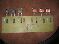
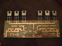
How you can see I spent $$$ on parts Toshiba transistors, Takman resistors 5W expensive resistors.
I have 4 board like that.
I would like to know how much a set PC board for a stereo amp with balanced or with out balanced input.
The schematic important to know if I can re use those parts.
I have more Toshiba transistors or I have IRFP to.
Can someone PM it to me. I promise I do not share it (or published) with nobody.
For these turbo version I would have a 1KVA transformer about 36 rail voltage.
Thank you
Greetings Gabor
Can someone share the schematic, I'm interested on a stereo set with balanced input.
I want to see if these project will exide my knowledge .
I did started my own balanced version long time a go but I never finished or tested.
It would be great if I can see from that project what I can use here.
How you can see I spent $$$ on parts Toshiba transistors, Takman resistors 5W expensive resistors.
I have 4 board like that.
I would like to know how much a set PC board for a stereo amp with balanced or with out balanced input.
The schematic important to know if I can re use those parts.
I have more Toshiba transistors or I have IRFP to.
Can someone PM it to me. I promise I do not share it (or published) with nobody.
For these turbo version I would have a 1KVA transformer about 36 rail voltage.
Thank you
Greetings Gabor
Attachments
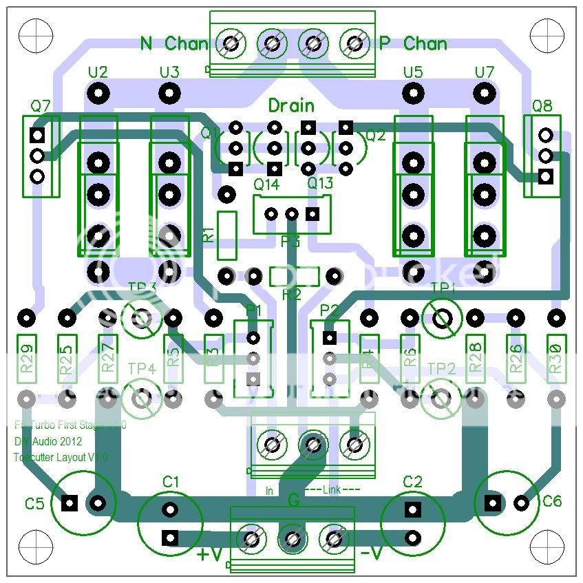
UKToecutter: Thanks for the post on the dimensions and current layouts.
Good work. I particularly like the idea of the single mosfet board to allow optimization for a specific heatsink.
It good to see someone else appreciate this. I'm starting to be concerned about people's repsonse to the V3 changes. I'm not even sure whether most of people zooming through this busy thread are realizing what that is for. Even for those who understands it, the prospect of some simplest P toP seems to be scaring them off. When PAPA first introduce F5, he mentioned that "I know most of you are not even going to consider buidling anything until PCB is on hands."
Don't want to be a smart ***, but I'm afraid, by the time amp building is on, many people might find out their heatsinks are not exactly up to the task, and then they will realize the size and shape of sink doesn't match their V3 output board, so one device is at 50 and the other is 70C and they can't jack up the bias anymore. And they will find they are getting class A only upto 50W not 100W they wanted and find that amp does not sound as good as they thought it would on their not-so-efficient speakers. Many might not even realize why that happened....
Last edited:
The thing is that in the initial article for F5, everything was really specified everything like rail voltage, psu config and heat sink requirement. So there was not much to be confused about and it was relatively easy to find sinks that are upto the task. But F5T is all about choices and compromises and finding out what their speakers requires and designing their own version of F5T. So it might be reasonable to expect some failure in the process, if one does not plan carefully. I feel like i now understand why PAPA took so long to release high power version of F5. If it were released too early before people understand F5 enough, there would have been lots of confusion...
Last edited:
UKToecutter:
The V2Combo board would have much better distribution of the heat if the mosfets
could be uniformly spaced about 65 mm apart rather than 50-100-50. It looks like the layout would allow this.
This makes a lot of sense if feasible. This way one could use all the boards with the same heatsink.
Andy
The input boards are not suitable for the balanced version. In Nelson's schematic the feedback loops are not connected to ground but to each other. However, perhaps a jumper could be incorporated so that the centre pin of P3 could either go to ground or to the centre pin of P3 on the associated board. Or have I got it all wrong?
Chalk
UKToecutter:
The V2Combo board would have much better distribution of the heat if the mosfets
could be uniformly spaced about 65 mm apart rather than 50-100-50. It looks like the layout would allow this.
only if 1 heatsink is used. most will use 2 heatsinks side by side. then its best as it is.
It good to see someone else appreciate this. I'm starting to be concerned about people's repsonse to the V3 changes. I'm not even sure whether most of people zooming through this busy thread are realizing what that is for. Even for those who understands it, the prospect of some simplest P toP seems to be scaring them off. When PAPA first introduce F5, he mentioned that "I know most of you are not even going to consider buidling anything until PCB is on hands."
Don't want to be a smart ***, but I'm afraid, by the time amp building is on, many people might find out their heatsinks are not exactly up to the task, and then they will realize the size and shape of sink doesn't match their V3 output board, so one device is at 50 and the other is 70C and they can't jack up the bias anymore. And they will find they are getting class A only upto 50W not 100W they wanted and find that amp does not sound as good as they thought it would on their not-so-efficient speakers. Many might not even realize why that happened....
Not as scary as those who will attempt to have 100 watt/ bias/ ch class-a amp .....for the first time ...
Not for the weak ......
Andy
The input boards are not suitable for the balanced version. In Nelson's schematic the feedback loops are not connected to ground but to each other. However, perhaps a jumper could be incorporated so that the centre pin of P3 could either go to ground or to the centre pin of P3 on the associated board. Or have I got it all wrong?
Chalk
Chalk,
I'll have a look at that now
It good to see someone else appreciate this. I'm starting to be concerned about people's repsonse to the V3 changes. I'm not even sure whether most of people zooming through this busy thread are realizing what that is for. Even for those who understands it, the prospect of some simplest P toP seems to be scaring them off. When PAPA first introduce F5, he mentioned that "I know most of you are not even going to consider buidling anything until PCB is on hands."
Don't want to be a smart ***, but I'm afraid, by the time amp building is on, many people might find out their heatsinks are not exactly up to the task, and then they will realize the size and shape of sink doesn't match their V3 output board, so one device is at 50 and the other is 70C and they can't jack up the bias anymore. And they will find they are getting class A only upto 50W not 100W they wanted and find that amp does not sound as good as they thought it would on their not-so-efficient speakers. Many might not even realize why that happened....
In fact, with the 3 position terminal block it's so simple to wire even I could do it !!!
- Status
- This old topic is closed. If you want to reopen this topic, contact a moderator using the "Report Post" button.
- Home
- Amplifiers
- Pass Labs
- F5 Turbo Circuit Boards