F5T (V3) Balanced SMD
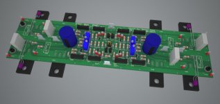
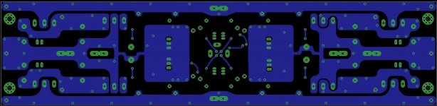
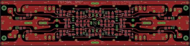
I have been working on a P5T PCB using mainly SMD components in the small signal path (MELF resistors, 1206 also possible). It started out as in Nelson Pass' Turbo article, but has evolved with inspiration of EUVL's work on F5X.
Planned specs:
- Bias 1.2A - 1.5A
- PSU: 2x625VA, 18V AC secondaries, DIYA Store Boards
- Modu / Deluxe 5U 400mm Chassis
Some of the decisions on this design may be overkill / unnecessary (e.g. cascaded input stage), but I like to have room for future modification/tuning. Also, the value of the BE-resistors of the protection BJTs have to be updated in the schematics. NP uses 150Ohms in stock F5, but with the turbo diodes I believe they should be increased up to 3k-4k for Rx17/Rx20, for limiting to ~0.75V over source resistor/diode parallel connection (10A@60C?). Are they populated / which values are used on the DIYA store boards?
Any useful feedback for (hopefully minor) modification would be greatly appreciated before I order boards.
Thanx a lot,
xLoff
Attachments
-
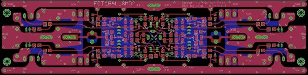 F5T_BAL_SMD_RC6_all.jpg129.4 KB · Views: 511
 -
F5T_BAL_SMD_RC6_sch.pdf36.6 KB · Views: 158
-
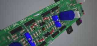 F5T_BAL_SMD_RC6_004.jpg51.8 KB · Views: 233
 -
 F5T_BAL_SMD_RC6_003.jpg29.7 KB · Views: 223
 -
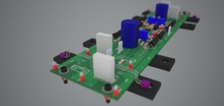
 F5T_BAL_SMD_RC6_002.jpg37.9 KB · Views: 464
 -
 F5T_BAL_SMD_RC6_001.jpg48.2 KB · Views: 475
 -
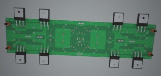
 F5T_BAL_SMD_RC6_btm.jpg68.7 KB · Views: 460
 -
 F5T_BAL_SMD_RC6_top.jpg126.2 KB · Views: 475
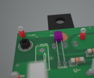
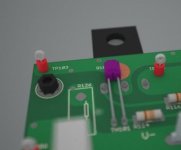
Use 1206 Susumu RG or Vishay TNPW. Spec wise, you have to spend a lot of money to beat them. Also check out Isabellenhuette PBH for your power resistors, same thing applies. I am not sure the legs on your thermistor will allow you to stretch that far. May be able to go under tha board. I have considered an uncovered pad right at drain pin to attach it to. This should give pretty good thermal coupling to the heat the fet is seeing.
Tsk, tsk, tsk... you are such a disappointment. Sort out your priorities man!...I blew all my funds for this month on some tubes for my Tetra and Aikido and restoring and old Linn LP12.

11W of ClassA into 8r0 requires a Maximum ClassA current of 1.66A
18W of ClassA into 8r0 requires a Maximum ClassA current of 2.13A
What does this mean?
18W of ClassA into 8r0 requires a Maximum ClassA current of 2.13A
What does this mean?
Output bias current through each output device? Or quiescent current into the whole amplifier, or something else?1.2-1.5A bias in balanced mode
1.2A of total output bias in each half of a balanced amplifier results in 2.4A of peak ClassA current through the load of a balanced amplifier.in balanced mode each half will see 4ohm with a 8ohm load.
1.2A bias=2.4A peak current. 1.5A bias=3A peak current.
2.4*0.707=1.7A
1.7*1.7*4=11.56W
2.4^2 * 4 ~ 23W of ClassA into an 8ohms speaker load. Not 11W
Each half of the balanced amplifier is delivering an effective 11.5W into the effective 4r0 half load.
Similarly 1.5A bias into one half of the balanced amplifier results in a maximum 36W of ClassA into an 8r0 load.
F5T (V3) Balanced SMD [II]
Thanks for the replies. I was mainly hoping for some PCB layout hints and feedback, not to start a theory discussion (enough of other posts of textbooks on this topic).
Thanks, I’m finally getting there… I prefer SMD as I have more experience with SMD PCBs, mainly high speed switching stuff though. They have smaller footprint, less parasitic (lead) inductance, don’t require though-hole drillings (messing up potential ground plane) etc. These are usually not critical for audio, but without compensation the F5 BAL may have gain up to 3 – 5 MHz.
Fancy specs, alright. At 10mg, they cost more than gold per gram...
Thanks, good point: On the 3D-model the legs are way too long. You mean attach it to the PCB at Drain right next to the soldered pin? (neat)
I hope to bring it up to 40W Class A, if the temperature on the heatsink allows it. I already have the cascodes there, so if necessary for future speakers, I could also increase the rail voltages. However, I use a different calculation than you.
My main concern is, like flg pointed out, is the maximum current. Also, the grandmaster mentioned the SOA of the 2SK/2SJs in the turbo article. From a simulation, I expect other distortion mechanisms to dominate before Class-A crossover.
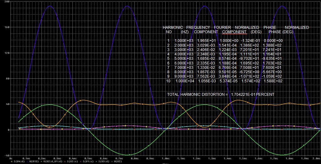
Input signal 4.1V sine at 1kHz, 8 Ohms output. Blue = load power, Green = differential load voltage, Orange = Positive output HS PMOS power, rest: current though all 4 FETs (overlaying). At 3V VIN, same circuit simulation gave ~3.8E-02 THD. [calculation of output power left as an exercise to the reader]
Regards,
xLoff
Thanks for the replies. I was mainly hoping for some PCB layout hints and feedback, not to start a theory discussion (enough of other posts of textbooks on this topic).
Originally Posted by pcb121055:
wow! that looks like a well executed project, xLoff. why smd?
Thanks, I’m finally getting there… I prefer SMD as I have more experience with SMD PCBs, mainly high speed switching stuff though. They have smaller footprint, less parasitic (lead) inductance, don’t require though-hole drillings (messing up potential ground plane) etc. These are usually not critical for audio, but without compensation the F5 BAL may have gain up to 3 – 5 MHz.
Originally Posted by buzzforb:
Use 1206 Susumu RG or Vishay TNPW. Spec wise, you have to spend a lot of money to beat them.
Fancy specs, alright. At 10mg, they cost more than gold per gram...
Originally Posted by buzzforb:
I am not sure the legs on your thermistor will allow you to stretch that far. May be able to go under tha board. I have considered an uncovered pad right at drain pin to attach it to. This should give pretty good thermal coupling to the heat the fet is seeing.
Thanks, good point: On the 3D-model the legs are way too long. You mean attach it to the PCB at Drain right next to the soldered pin? (neat)
Originally Posted by AudioSan:
23-24V rails. and 1.2-1.5A bias in balanced mode. this will be a very low biased V3 class A/B version. 11-18W class A at 8ohm. and around 140W class A/B at 8ohm.
I hope to bring it up to 40W Class A, if the temperature on the heatsink allows it. I already have the cascodes there, so if necessary for future speakers, I could also increase the rail voltages. However, I use a different calculation than you.
My main concern is, like flg pointed out, is the maximum current. Also, the grandmaster mentioned the SOA of the 2SK/2SJs in the turbo article. From a simulation, I expect other distortion mechanisms to dominate before Class-A crossover.
Input signal 4.1V sine at 1kHz, 8 Ohms output. Blue = load power, Green = differential load voltage, Orange = Positive output HS PMOS power, rest: current though all 4 FETs (overlaying). At 3V VIN, same circuit simulation gave ~3.8E-02 THD. [calculation of output power left as an exercise to the reader
]Regards,
xLoff
Attachments
1.2A of total output bias in each half of a balanced amplifier results in 2.4A of peak ClassA current through the load of a balanced amplifier.
2.4^2 * 4 ~ 23W of ClassA into an 8ohms speaker load. Not 11W
Each half of the balanced amplifier is delivering an effective 11.5W into the effective 4r0 half load.
Similarly 1.5A bias into one half of the balanced amplifier results in a maximum 36W of ClassA into an 8r0 load.
peak Power is realy not the mark to use is it?
so. its more like:
2.4^2 * 4 / 2 =11.5W
or the one you always INSIST to use.
(2.4*0.707)^2*4=11.5W average at 8ohm load.
F5T (V3) Balanced SMD [III]
With all the respect, please start another thread for calculating the Class A output power of the F5T (with the turbo diodes). I would also like to get into that topic [my two cents: stop treating the current as a constant, but rather a variable. Better reach out for some differential equations and/or redefine your definition of Max Class A power], but first I want to focus on this treads’ target - F5 Turbo Circuit Boards.
AudioSan: you are right, but I already got my 24V AC x-formers waiting. I am also worried that increasing the bias current may push up the max diode current under certain conditions. Controlling the maximum diode current I my first priority. Curve tracing the diode/resistor pair over temperature may be clever. Anyone tried to degenerate the diodes???
Regards,
xLoff
With all the respect, please start another thread for calculating the Class A output power of the F5T (with the turbo diodes). I would also like to get into that topic [my two cents: stop treating the current as a constant, but rather a variable. Better reach out for some differential equations and/or redefine your definition of Max Class A power], but first I want to focus on this treads’ target - F5 Turbo Circuit Boards.
AudioSan: you are right, but I already got my 24V AC x-formers waiting. I am also worried that increasing the bias current may push up the max diode current under certain conditions. Controlling the maximum diode current I my first priority. Curve tracing the diode/resistor pair over temperature may be clever. Anyone tried to degenerate the diodes
???Regards,
xLoff
Last edited:
you are driving an 8ohm load.peak Power is realy not the mark to use is it?
so. its more like:
2.4^2 * 4 / 2 =11.5W
or the one you always INSIST to use.
(2.4*0.707)^2*4=11.5W average at 8ohm load.
The peak current is 2.4Apk, the rms current is 1.7Aac
P=2.4^2*8/2 or P=1.7^2*8
Both come to 23W.
This is not an instantaneous peak power. It is the average power delivered to a resistive load.
you are driving an 8ohm load.
The peak current is 2.4Apk, the rms current is 1.7Aac
P=2.4^2*8/2 or P=1.7^2*8
Both come to 23W.
This is not an instantaneous peak power. It is the average power delivered to a resistive load.
each half of a balanced or X'ed amp see half the impedance.
so a 8ohm load will be seen as a 4ohm load for each half.
you need to calculate as if it was 4ohm load. then you will get 11.5W.
Yes, each half of a balanced amp only needs to swing half the total voltage, but delivers the full current to the load. That accounts for the "each amp sees a 4 ohm load" Remember, that a push pull amp can deliver twice its idle current before leaving class A, so 1.2A total bias per side yields 2.4 A output current peak. From the 8 ohm load perspective, you're still seeing the 2.4A peak/1.7A RMS. From there it is simple math.which yields 23W RMS.
Were you interpreting the stated bias as total or per side of a balanced amp? Perhaps you and Andrew and I are starting from different points, which would explain the disparity. .
Were you interpreting the stated bias as total or per side of a balanced amp? Perhaps you and Andrew and I are starting from different points, which would explain the disparity. .
- Status
- This old topic is closed. If you want to reopen this topic, contact a moderator using the "Report Post" button.
- Home
- Amplifiers
- Pass Labs
- F5 Turbo Circuit Boards