AudioSan said:With 23-24V rails. and 1.2-1.5A bias in balanced mode. this will be a very low biased V3 class A/B version. 11-18W class A at 8ohm. and around 140W class A/B at 8ohm.
That's why I asked what Aud meant with "in balanced mode". So that we were both on the same page.......................Were you interpreting the stated bias as total or per side of a balanced amp? Perhaps you and Andrew and I are starting from different points, which would explain the disparity. .
Once Aud defined his bias, I waded in with the correct power calculation.
To clarify: plan is to dimension the idle bias current in each half bridge up to 1.5A. However, I do not plan to limit the maximum class A operation according to:
It’s push pull alright, but you could push more current than twice the idle current, while still keeping on pulling some (and avoiding leaving class A, causing crossover distortion). A non-linear idle / peak current relation is called for. [my classification of Class A is not strictly limited to delivering up to 2 x idle current, but rather to point where one transistor in the half-bridge (or H-bridge) pinches off]
-- xLoff
Originally Posted by BobEllis:
a push pull amp can deliver twice its idle current before leaving class A, so 1.2A total bias per side yields 2.4 A output current peak. From the 8 ohm load perspective, you're still seeing the 2.4A peak/1.7A RMS. From there it is simple math.which yields 23W RMS.
It’s push pull alright, but you could push more current than twice the idle current, while still keeping on pulling some (and avoiding leaving class A, causing crossover distortion). A non-linear idle / peak current relation is called for. [my classification of Class A is not strictly limited to delivering up to 2 x idle current, but rather to point where one transistor in the half-bridge (or H-bridge) pinches off]
-- xLoff
Xloff,
both transistors in a push pull arrangement must actively control the currents passing through the stage and to the output to remain in ClassA.
If one or other of the transistors moves to an idle state, whether passing current or turned off, then the stage is no longer operating in ClassA.
both transistors in a push pull arrangement must actively control the currents passing through the stage and to the output to remain in ClassA.
If one or other of the transistors moves to an idle state, whether passing current or turned off, then the stage is no longer operating in ClassA.
F5T V2.... almost ready
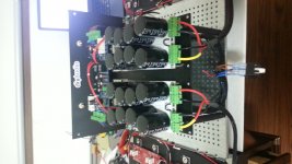
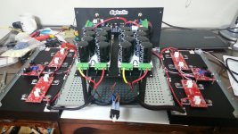
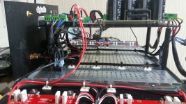
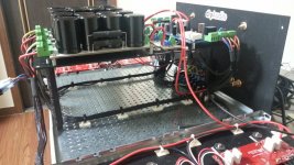
I am almost ready to power on my F5T.
Missing very few thinks... the hole in the front panel (22 mm... not easy), 1 CL60 that I can't find here and the 2 trafos (buuuuzz... ).
).
Now I am really nervous thinking to the first power on and the bias... I will sure back to some help!
Many thanks everyone that partecipate to this amazing project.... to Buzz for the GB, TeaBag, Patrick and 6L6 for the supports given me time to time. And offcourse NP")
Ciao
Enrico
I am almost ready to power on my F5T.
Missing very few thinks... the hole in the front panel (22 mm... not easy), 1 CL60 that I can't find here and the 2 trafos (buuuuzz...
).Now I am really nervous thinking to the first power on and the bias... I will sure back to some help!
Many thanks everyone that partecipate to this amazing project.... to Buzz for the GB, TeaBag, Patrick and 6L6 for the supports given me time to time. And offcourse NP
Ciao
Enrico
Attachments

I am almost ready to power on my F5T.
Missing very few thinks... the hole in the front panel (22 mm... not easy), 1 CL60 that I can't find here and the 2 trafos (buuuuzz...
Now I am really nervous thinking to the first power on and the bias... I will sure back to some help!
Many thanks everyone that partecipate to this amazing project.... to Buzz for the GB, TeaBag, Patrick and 6L6 for the supports given me time to time. And offcourse NP
Ciao
Enrico
I will throw a CL60 in your box .
Thanks Walter and Audiosan.
As I said I am quite nervous for the bias.
Cheers
Enrico
just take it up nice and slow. and let the sinks warm up between each adjustment.
but when do you get your trafos? Then you should be nervous....
Just make sure the bias trimmers are in the right position before you start...I measured every potentiometer twice with the ohmmeter just to be sure..
But you are right it's always a very exciting moment switching the 230V... those big donuts can destroy everything...
Just make sure the bias trimmers are in the right position before you start...I measured every potentiometer twice with the ohmmeter just to be sure..
But you are right it's always a very exciting moment switching the 230V... those big donuts can destroy everything...
Last edited:
I already test the 2 sofstart and the speaker protection.
I test also the 2 PSU with a small trafo 100VA 12-0-12 that is ready for the mesmerize DCB1 and everything is fine...as Walter say who scare me are this small donuts.
All test done starting with the light bulb tester
Thanks guys for your nice support
Enrico
I test also the 2 PSU with a small trafo 100VA 12-0-12 that is ready for the mesmerize DCB1 and everything is fine...as Walter say who scare me are this small donuts.
All test done starting with the light bulb tester
Thanks guys for your nice support
Enrico
Little update
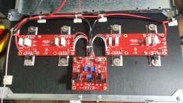
As I say I already test the 2 PSU that give me 15.6 V. So.... I can' t wait and today I give power to the amplifier and look like so far everything is working well.
I have only 2 meters that I use for test the bias regolation. The pots are working and nothing is smoking. I can reach 600 mV before the PSU seat down. The heatshink get a little warm.
What I notice is that increasing the pots of one side increase also the other side and I suppose that is normal.
Having only 2 meters I check time to time the offset that is quite high... maximum that I read is 438 mV. With the third meter and the correct PSU I will bias properly
I know that is not the correct test to do but now I know that is working and I am more quiet.
Ciao
Enrico
What I notice is that increasing the pots of one side increase also the other side and I suppose that is normal.
Enrico
That's normal.
If you have two meters like me, I used one meter for the offset and one to measure the voltage over one of the source resistors.
Then turn up the bias with one pot, offset increases, and turn offset to zero with the other pot... and so on... slowly, slowly, slowly
- Status
- This old topic is closed. If you want to reopen this topic, contact a moderator using the "Report Post" button.
- Home
- Amplifiers
- Pass Labs
- F5 Turbo Circuit Boards