Looks like there was a rough surface or debris between the fet and the heatsink. One potential problem area is a raised area where the hole was tapped. If you tapped the holes yourself you need to make sure the edge is chamfered so there are no high spots that can cause a short. If you remove the FET and pad you may be able to determine where the problem started.
Looks like there was a rough surface or debris between the fet and the heatsink. One potential problem area is a raised area where the hole was tapped. If you tapped the holes yourself you need to make sure the edge is chamfered so there are no high spots that can cause a short. If you remove the FET and pad you may be able to determine where the problem started.
The holes are/where pre drilled / machined by HIFI 2000, as it is a DIYaudio 5U chassis kit. All areas for the fets were finished back to ali (removing anodizing) for the best 'intimate contact' with 600 wet and dry by myself then cleaned with alcohol solution.
So my question is what else would/could have suffered...it was a P, the last fet (furthest from FE board.) I will be replacing all 4 P's though. eeerrrrr
Last edited:
I solved the problem by myself, but I have a little problem left. If I switch the amp on, it hums a little and if I knock with my finger on the front casing the hum sound is completely gone. If I switch it off and on again it's there again... Is my Volume Potentiometer faulty ? (It's an old Alps 100K). Or do I still have problems with the earthing ?
regards[/QUOTE Try to earth the Alps
The holes are/where pre drilled / machined by HIFI 2000, as it is a DIYaudio 5U chassis kit. All areas for the fets were finished back to ali (removing anodizing) for the best 'intimate contact' with 600 wet and dry by myself then cleaned with alcohol solution.
So my question is what else would/could have suffered...it was a P, the last fet (furthest from FE board.) I will be replacing all 4 P's though. eeerrrrr
I'm also building 2 F5turbo monos so it's pretty scary to see a failure like that. Since it happened at power up it's not likely a breakdown of the FET due to heat. One other thing that comes to mind is the mounting bolt torque. If too much torque was used it could possibly compromise the pad. I guess the mosfet itself could have had a small piece of debris on it's back side that caused a short.
Was a speaker connected at the time? If the speaker did not receive a big pulse from the amp it probably means that the N side of the amp kept the voltage down on the output until the power supply collapsed. Since there are 4 fets to share the load they probably survived.
After repairing the amp I would run it with a dummy load for several thermal cycles before putting it back into service.
Keep us posted. I hate mystery failures like this. If anyone else has experienced this failure mode on F5T or has a theory for why it happened please provide input so we all can learn.
So Ive spent a pleasant day on a strip down and diagnostic interrogation....
I cant find any reason apart from a short via the sil pad for this. What is now apparent is that all fets N & P are US along with the jfets...47r5 resistors are all blown..


though the MUR3020 diodes seem to be OK? I will be rebuilding all the boards with new components in due course using mica pads and a bit of thermal paste, old fashioned I know but.....and I think mounting bolt torque could be an issue here...not that theres any evidence. Not sure how to gauge 'how much torque' is needed, a firm 'nip' is all Ive used (with success) for many years. Could it have just been a defective mossfet??? The boards, after a clean, have survived unscathed which must be a testament to their quality.
Yes, the speakers (Martin Logans ESL's) were connected and they have survived (amazing!!!) Upon rebuild the I will cycle up a few times with a load before pressing into service..
Last edited:
I would have suspected a metal short off the back of the knowledge that you hand-sanded the mating surface, but a burnt gate resistor is evidence that the amplifier was oscillating. The back of the metal case is clean and untouched, if there was physical contact that would have been blackened.
Also the melted source terminal indicates you have some sort of high-frequency/current feedback path through the power supply. Do go over your wiring, and install the optional compensation capacitors as mentioned in the article.
The diodes should be fine, they can survive major abuse.
At the kind of thermal loads we are talking about, Sil-pads are totally avoidable. You're simply asking for trouble due to their very high thermal resistance. I would actually not be surprised if it was a thermal issue that fused the gate-source junction.
It could be a few different things at this point, so examine all the evidence carefully.
Hello guys, I might need a little help from you...
I am going to build the v2 turbo and ordering all the parts. The F5 PCBs and 5U case (directly from modushop, not diyaudio Deluxe predrilled) have already arrived, but as the diyaudioshop is short of the PSU boards, I have to find some for myself...
So as I don"t want to wait several month for PCBs to arrive from china (Jims audio store) I was thinking to order the from germany (Thel audio shop).
I have two options:
1. A plane rectifier bridge with capacitor bank 20 x 6800uF 50V (STP-6,8/50)

or
2. Regulated PSU 5-55V DC with 8A effective current and 20A peak with ripple voltage of +/- 1mV (SPR-8.2)
What do you think, could I use the regulated PSU for the F5 turbo v2?
Thank you in advance!
I am going to build the v2 turbo and ordering all the parts. The F5 PCBs and 5U case (directly from modushop, not diyaudio Deluxe predrilled) have already arrived, but as the diyaudioshop is short of the PSU boards, I have to find some for myself...
So as I don"t want to wait several month for PCBs to arrive from china (Jims audio store) I was thinking to order the from germany (Thel audio shop).
I have two options:
1. A plane rectifier bridge with capacitor bank 20 x 6800uF 50V (STP-6,8/50)
or
2. Regulated PSU 5-55V DC with 8A effective current and 20A peak with ripple voltage of +/- 1mV (SPR-8.2)
An externally hosted image should be here but it was not working when we last tested it.
What do you think, could I use the regulated PSU for the F5 turbo v2?
Thank you in advance!
You could probably use both of these units. However, the F5T commonly uses a CRC or CLC supply. You could easily build one from scratch for much less money that the Thel stuff. Just head over to mouser.com or similar to get your parts within a few days (rectifiers, caps, power resistors or chokes). If you want to build without a PCB (no waiting for PCBs getting available), your could use copper strips and screw-terminal electrolytics.
Update on the blown fet. I have know idea why the offending fet let go other than a thermal issue!!???. The defective part/s replaced (that was all the mosfets and a quad set of jets) heat sinks cleaned again all pads (after due concideration) replaced with with kermatherm silicone fiberglass.
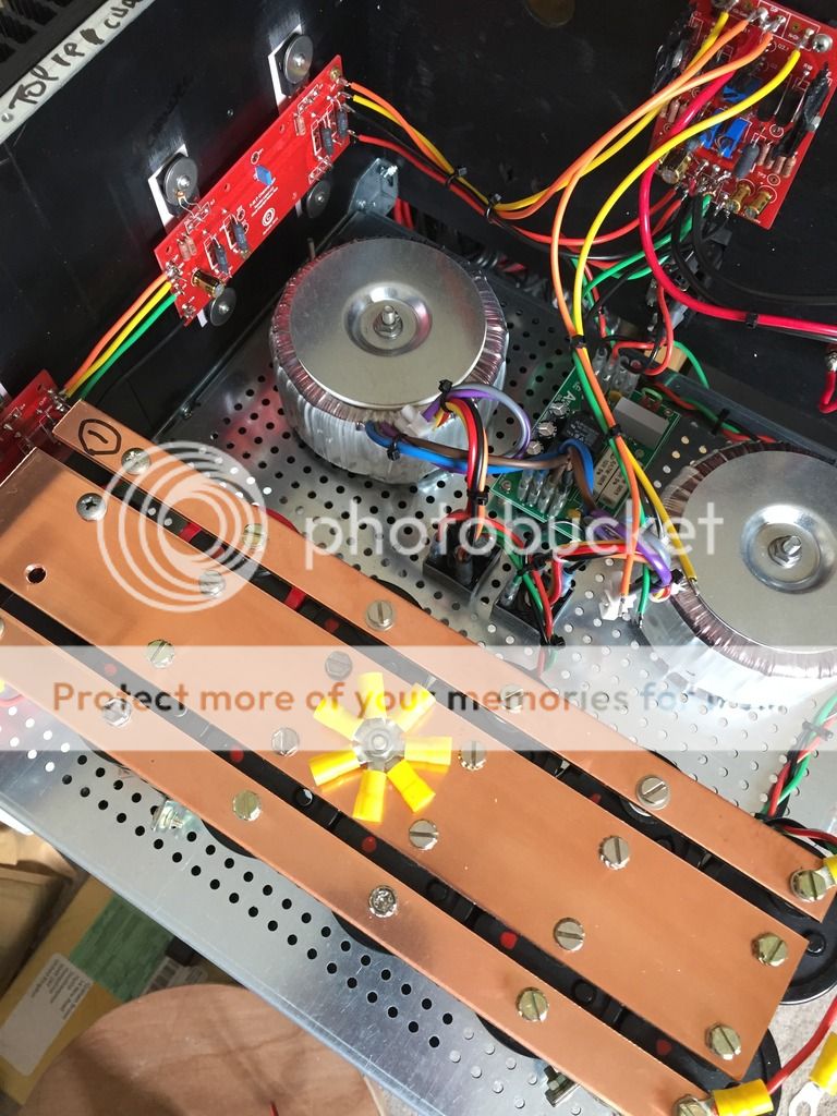
All wiring checked, checked and checked again & while I was at it a bit of star earthing. Not sure if its worth it, I see many doing it this way, so why not.
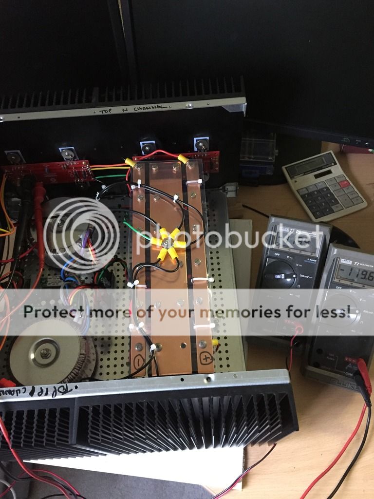
Alls well now and back making sounds...happy bunny...
I do have reservations on my transformer size (VA) and have some 625VAs on their on way to replace the 325va I'm currently running..
You could probably use both of these units. However, the F5T commonly uses a CRC or CLC supply. You could easily build one from scratch for much less money that the Thel stuff. Just head over to mouser.com or similar to get your parts within a few days (rectifiers, caps, power resistors or chokes). If you want to build without a PCB (no waiting for PCBs getting available), your could use copper strips and screw-terminal electrolytics.
Couldn't agree more with the above. I have in the past used regulated PSU's in various power amps and they seem to 'sit' on the sound. IMO
Couldn't agree more with the above. I have in the past used regulated PSU's in various power amps and they seem to 'sit' on the sound. IMO
Looking at the above photos from laverda, it does look very nice and clean with the copper rails...
But still, maybe someone could tell me why it is not preferred to use regulated PSUs...
maybe someone could tell me why it is not preferred to use regulated PSUs...
Maybe its not required, Mr Pass did not specify or suggest a regulated supply in the F5t paperwork. I would imagine he has tried them in the past..(or in other applications) I don't know but do try it and report back please.
The question and answers on the absence of a regulated power supply can also be found here
AMB Laboratories DIY Audio • View topic - Informative questions before starting ?24 build
AMB Laboratories DIY Audio • View topic - Informative questions before starting ?24 build
The question and answers on the absence of a regulated power supply can also be found here
AMB Laboratories DIY Audio • View topic - Informative questions before starting ?24 build
Ok, thank you. I think i'm gonna stick to an already proven concept and not make any experiments with regulated PSU
")
Quick update on my progress with the rebuild of the blown amp and recommissioning. Ever thing is A OK.
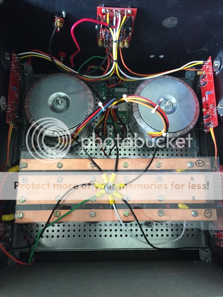
While it was in bits I star earthed all the 0v returns back to the center rail and swapped out the existing 325va transformers per rail for 625va. Big lift in sound stage with an added delicacy. So it was worth it, I wasn't sure it would be, but it is.

While it was in bits I star earthed all the 0v returns back to the center rail and swapped out the existing 325va transformers per rail for 625va. Big lift in sound stage with an added delicacy. So it was worth it, I wasn't sure it would be, but it is.
- Home
- Amplifiers
- Pass Labs
- F5 Turbo Builders Thread