As an experiment, I tried to change the source resitor to the FET I measured only 140mV. A resistanse of 0,4646 ohm was changed to 0,5855 ohm . This increased the bias from 140 mV to 190 mV. I am temted to try 0.68 ohm to come closer to 270 mV. Is this a recommended(and easy) way to get better bias balance on the FETSs?
Eivind S
You shouldn't run uneven source resistors. They all should be the same. Re measure the fets at higher current. That will tell you if they are really matched or not.
My F5 is now finished, but I have a little problem now, when the power is on there is a silent hum sound on my right channel. If I connect only the left side of my F5 there is no hum sound at all. When I connect both of them and I touch my Case of the Amp the hum sound is also gone. Whats the meaning of this ?
My F5 is now finished, but I have a little problem now, when the power is on there is a silent hum sound on my right channel. If I connect only the left side of my F5 there is no hum sound at all. When I connect both of them and I touch my Case of the Amp the hum sound is also gone. Whats the meaning of this ?
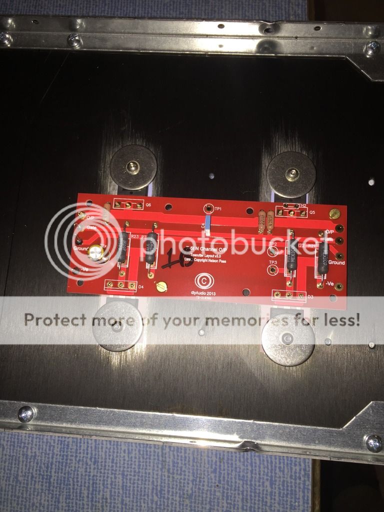
Picture please
not overly significant , as long you didn't use oldest one , pulled from Grand Ma's radio
I'm finding modern SMD ceramics good for that position
buy biggest SMD format you can find , solder two tiny legs on it and there is through hole cap
both cheap and good , who could ask for more
I'm finding modern SMD ceramics good for that position
buy biggest SMD format you can find , solder two tiny legs on it and there is through hole cap
both cheap and good , who could ask for more
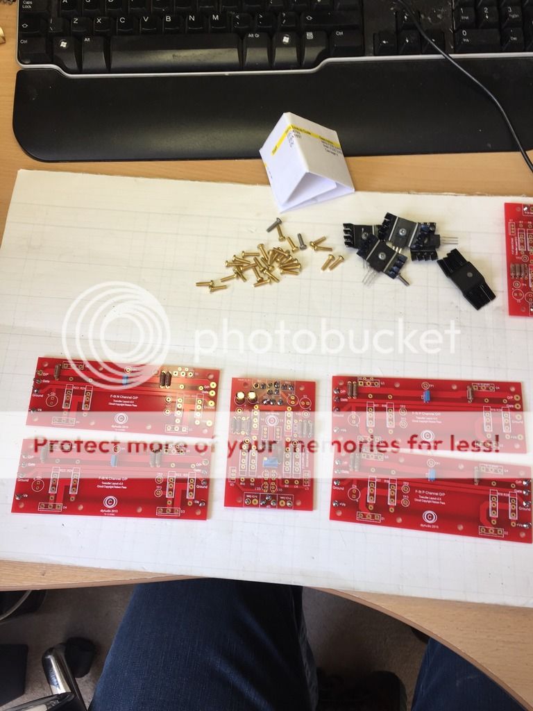
My mono V3 build has started...
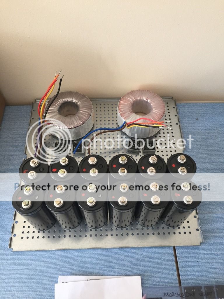
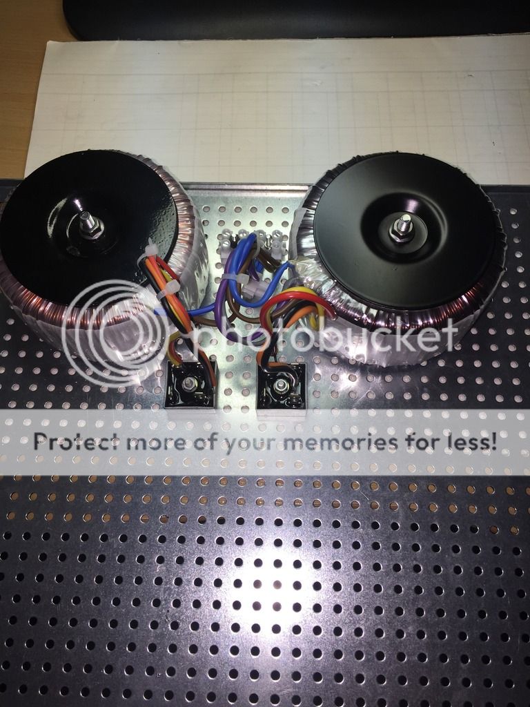
2 off 300va 0-35 0-35 transformers, so 48v rails. The caps are 15,000uf 63v 6 per rail giving a total of 90,000uf per rail.
Clean surfaces for intimate contact for the mosfets..
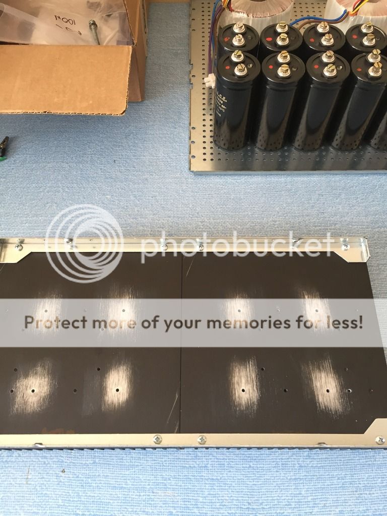
dry run..
more stuffing going on.
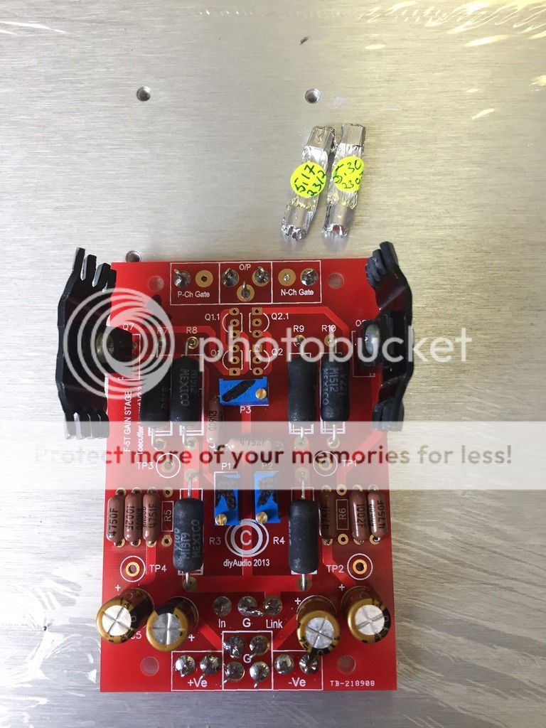
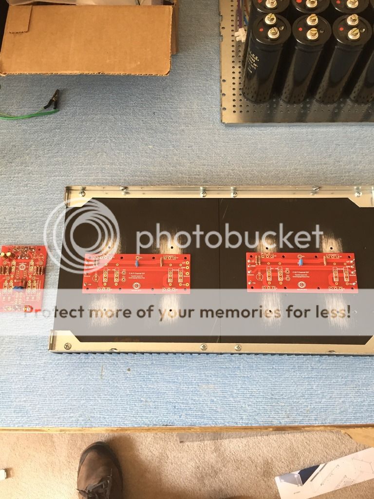
Quad jfets...ready to go in...
jfets in, R5 & 6 not stuffed yet but will be shortly...
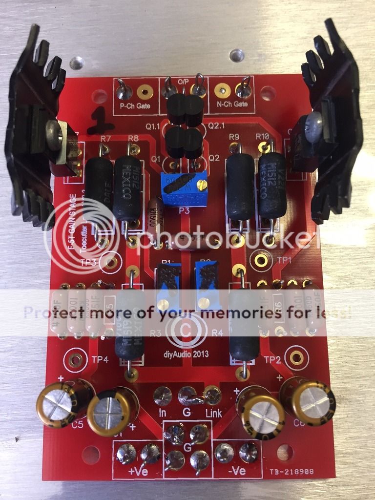
Work in progress....more to follow.


2 off 300va 0-35 0-35 transformers, so 48v rails. The caps are 15,000uf 63v 6 per rail giving a total of 90,000uf per rail.

Clean surfaces for intimate contact for the mosfets..


dry run..

more stuffing going on.

Quad jfets...ready to go in...

jfets in, R5 & 6 not stuffed yet but will be shortly...
Work in progress....more to follow.
Last edited:
2 off 300va 0-35 0-35 transformers, so 48v rails. The caps are 15,000uf 63v 6 per rail giving a total of 90,000uf per rail.
Excuse the ignorant Qu, laverda but if you are building mono v3s ... why are there 2 power transformers in that case?
Or are you building a dual-mono v3 (so 2 entirely separate channels ... just in the same case)?
Thanks,
Andy
Excuse the ignorant Qu, laverda but if you are building mono v3s ... why are there 2 power transformers in that case?
Or are you building a dual-mono v3 (so 2 entirely separate channels ... just in the same case)?
Thanks,
Andy
Andy,
One for the + rail, one for the - rail. I don't know if its over the top (300va per rail) Though I see some use 700-1kva transformers. I had two transformers anyway doing nothing. Bit of a suck it and see really, if it works and sounds any good.
Graham
If you are building your F5T as a ClassA amplifier then expect the transformer to be 6 to 10times a s much as the total maximum output power.
Two 300VA transformers would allow 600/10 = 60W to 600/6 = 100W of total maximum power.
A stereo F5 @ 27W output needs at least 300VA and I suspect many Builders use 500VA.
Two 300VA transformers would allow 600/10 = 60W to 600/6 = 100W of total maximum power.
A stereo F5 @ 27W output needs at least 300VA and I suspect many Builders use 500VA.
Andy,
One for the + rail, one for the - rail. I don't know if its over the top (300va per rail) Though I see some use 700-1kva transformers. I had two transformers anyway doing nothing. Bit of a suck it and see really, if it works and sounds any good.
Graham
Aah OK, Graham - yes, gives you more current delivery. I presume you use both secondaries of each trafo in parallel, so you get 8.5a from each?
And why did you use a toroid rather than an EI, say - which AIUI will not pass as much "mains nasties" as a toroid?
If you are building your F5T as a ClassA amplifier then expect the transformer to be 6 to 10 times as much as the total maximum output power.
Two 300VA transformers would allow 600/10 = 60W to 600/6 = 100W of total maximum power.
Thanks, Andrew. I'm assuming that's 60-100w of power into 8 ohms?
If I want to be able to deliver, say, 8a into a 2-ohm load, I need to use 2x 200VA transformers with their 27v secondaries in parallel (1 trafo for the + rail, 1 for the - rail)?
Regards,
Andy
If you are building your F5T as a ClassA amplifier then expect the transformer to be 6 to 10times a s much as the total maximum output power.
Two 300VA transformers would allow 600/10 = 60W to 600/6 = 100W of total maximum power.
A stereo F5 @ 27W output needs at least 300VA and I suspect many Builders use 500VA.
Thanks for the info AndrewT. Sometimes the maths goes right over my head....But I'm learning.
How do you ascertain at what point the amp is in Class A or Not.
TIA
Aah OK, Graham - yes, gives you more current delivery. I presume you use both secondaries of each trafo in parallel, so you get 8.5a from each?
And why did you use a toroid rather than an EI, say - which AIUI will not pass as much "mains nasties" as a toroid?
Thanks, Andrew. I'm assuming that's 60-100w of power into 8 ohms?
If I want to be able to deliver, say, 8a into a 2-ohm load, I need to use 2x 200VA transformers with their 27v secondaries in parallel (1 trafo for the + rail, 1 for the - rail)?
Regards,
Andy
Yes, parallel config. There is the element of 'galvanic isolation' between rails also contributes to a sonic improvement. I have done this in the past but on a smaller scale and yes there was an improvement..
I had the transformers anyway...thats why I used them...
The impedance does not matter. It's the maximum ClassA power. You choose whether you want to drive an 8ohms speaker to full power in ClassA or a 4ohms speaker to full power in ClassA or a 2ohms speaker to full power in classA. You set your target, then predict what parameters you require from your amplifier to meet that target and then you can select transformers to meet those duties........... I'm assuming that's 60-100w of power into 8 ohms?
8Aac, or 8Apk?If I want to be able to deliver, say, 8a into a 2-ohm load, I need to use 2x 200VA transformers with their 27v secondaries in parallel (1 trafo for the + rail, 1 for the - rail)?.......
In ClassAB, or in ClassA?
I don't believe you have thought this through yet.
You seem to be grasping at numbers without understanding the consequences they imply.
Last edited:
Here is my F5Tv3 I'm building and the calculations I've gone through. If anyone sees any mistakes please correct me. ")
I'm using 35v 800va Anteks for my 4 pair/channel F5t v3's mono blocks to drive 6 ohm speakers which should yield approximately 90 watts class A with 0.7A/FET bias.
Using 1.3 as the multiplier to give the approximate voltage after the capacitors, taking into account the voltage drop under a class A load.
(E*1.3)
36.5vac x 1.3 = 47.5vdc under load (my A/C line runs a little high)
0.35mv across 0.5ohm degeneration resistors gives 0.7A per FET, with 8 FETs
(E/R*FETs)
0.35mv / 0.05ohms = 0.7A per FET
0.7A* 8 = 5.6A of available class A output.
We know the max class A current so to calculate the max voltage at that current before it switches to class AB
(I*R=E)
5.6A * 6ohm = 33vpk
Now calculate the max power in peak watts at the peak class A voltage
(E*E/R/2)
33^2 / 6 / 2 = 90.75 watts pk class A
also...
Heat produced by the FETs that needs to be removed by the heat sinks.
(I per FET * number of FETs * supply voltage). In my case I have 4 FETs per sink. 0.7A * 4 * 47.5vdc = 133 watts of heat or 0.7A * 47.5vdc = 33.25 watts per FET. **It will be higher if running it over this in class AB.
A grand total of 266+ watts of heat produced per channel! Two mono blocks will warm a room pretty quickly (532+ watts of heat ) so you'll probably want to keep the windows open in the winter and a really good A/C system in the summer.
  I'm using the diyAudio store 5U chassis which has been proven to handle 130+ watts of heat per side.
and...
It will provide more than 90 watts in class AB with 43v pk output.
(E^2/R/2=P)
43vpk^2 /6 /2 = 154watts pk class AB
In reality it will not be able to hit this because as we draw more current from the xformer the voltage will drop more, depending on the xformer's capabilities, but close enough for calculations sake.
lastly...
We'll need to check max current at max output volts
(E/R=I)
43vpk / 6ohms = 7.17A total class AB current (which this xformer 'can' produce but it's going to get quite warm)
So it will be voltage limited ...Good
TJ
I'm using 35v 800va Anteks for my 4 pair/channel F5t v3's mono blocks to drive 6 ohm speakers which should yield approximately 90 watts class A with 0.7A/FET bias.
Using 1.3 as the multiplier to give the approximate voltage after the capacitors, taking into account the voltage drop under a class A load.
(E*1.3)
36.5vac x 1.3 = 47.5vdc under load (my A/C line runs a little high)
0.35mv across 0.5ohm degeneration resistors gives 0.7A per FET, with 8 FETs
(E/R*FETs)
0.35mv / 0.05ohms = 0.7A per FET
0.7A* 8 = 5.6A of available class A output.
We know the max class A current so to calculate the max voltage at that current before it switches to class AB
(I*R=E)
5.6A * 6ohm = 33vpk
Now calculate the max power in peak watts at the peak class A voltage
(E*E/R/2)
33^2 / 6 / 2 = 90.75 watts pk class A
also...
Heat produced by the FETs that needs to be removed by the heat sinks.
(I per FET * number of FETs * supply voltage). In my case I have 4 FETs per sink. 0.7A * 4 * 47.5vdc = 133 watts of heat or 0.7A * 47.5vdc = 33.25 watts per FET. **It will be higher if running it over this in class AB.
A grand total of 266+ watts of heat produced per channel! Two mono blocks will warm a room pretty quickly (532+ watts of heat
) so you'll probably want to keep the windows open in the winter and a really good A/C system in the summer. I'm using the diyAudio store 5U chassis which has been proven to handle 130+ watts of heat per side.and...
It will provide more than 90 watts in class AB with 43v pk output.
(E^2/R/2=P)
43vpk^2 /6 /2 = 154watts pk class AB
In reality it will not be able to hit this because as we draw more current from the xformer the voltage will drop more, depending on the xformer's capabilities, but close enough for calculations sake.
lastly...
We'll need to check max current at max output volts
(E/R=I)
43vpk / 6ohms = 7.17A total class AB current (which this xformer 'can' produce but it's going to get quite warm
)So it will be voltage limited ...Good
TJ
- Home
- Amplifiers
- Pass Labs
- F5 Turbo Builders Thread