Andrew, I have had it as far as 275 without any issue. I'm sure it will go much higher than that given the number of turns it took to get to that point. I am going to sit at 250mv to see how hot it gets after a few hours. So far I have not been able to monitor it for more than 1.5hrs. At 250 mv it is starting to get hot rather than warm but still less than 120f. The heatsink touch test is still saying it could take a bit more. Today, if I have the time, I'll start signal testing. I'm using a Jensen input transformer to get balanced inputs. I used 10k as an input resistor which is what the transformer requires for proper termination. Input capacitance has 1k in series so my hope is that the transformer will be happy with the input network as is.
The input transformer needs a load. It's the OUTPUT of the transformer that gets the 10k, if that is the value that Jensen recommend.
Is it an input transformer?
Yes, it's an input transformer Andrew and I have the amplifier input impedance set to it's required 10k rather than the 47k that the standard build specifies. Tests today show that it is pretty well terminated with just a single small overshoot on a 10khz square wave.
I got the amps both adjusted today and put everything together for a test listening session. I had to scramble to find 2 stands to stack the supply and amp cases on. I did some basic checks. Bandwidth is flat at 20khz,-3db at about 90k, -6 at 115 and -20 at 215khz. Flat at 20hz on the bottom end. Noise - I calculated it at about 60uv wideband. Dead quiet at the speaker in practice.
It sounded very nice. Since I haven't listened to the system for long I will refrain from making any judgements but it did seem to have that special way with sound stage size and decay of notes that I have noticed from other class A SS amps.
Couldn't listen for long, maybe an hour or so.
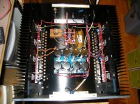
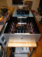
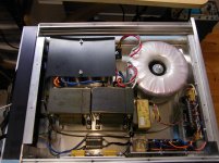
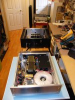
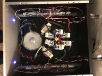
Heres a few pictures- It's a 4 box setup with mono blocks and separate power supplies with soft start circuitry. I mounted the input transformers , a Jensen JE-11P-1 in small blocks of cherry. I just couldn't use that thin angle bracket that they send with it. The power supply has a total of 240kuf/ch and 2 30mh chokes. About 46-47 volts dc with very low ripple maybe a couple of mv. The power switch is on the amplifier and a 1/8" cable connects it to the power supply box. A controller using a LM3914 sequences SSRs for first a series resistor, then in parallel with the resistor a CL 30 and finally a conventional relay bypasses the 2 SSRs and they are shut off. All of this with very little fuss from an LM3914. All analog, no programming or clock needed.
Attachments
Last edited:
Just a few notes on the F5 monos above. I did not use the diodes so I guess they would be a F5V3 without the turbo. Building a 4 box setup is a lot of work and building the power supply chassis from scratch was time consuming. I got the amp chassis from EBay and got them for a good price. Again, a lot of time was spent locating and drilling/tapping holes for the boards, Fets and connectors. I also had to spend a couple of quality hours flattening the brushed finish on the heatsink mounting surface so that I had a nice flat shiny surface to mount the IR 240/9240 fets. I felt this was time well spent due to the smallish size of the chassis/heatsinks. I am using the keratherm insulators sold in the store and used a small 1/4" drive torque wrench to set the mounting torque to 10 in/lbs. This is the max recommended in the Fet data sheet. The extra work seems to have paid off in good heat transfer. The fets do not feel much warmer than the heatsinks which are probably running in the 46-48c range when biased at my target bias of 250mv/.5amps. You could hold your hand on the FET indefinitely without it feeling too hot. Hopefully 10 in/lbs is no too much torque for the insulators. I had no failures on startup so time will tell I guess.
The lesson here is that if you value your time, seriously consider buying the pre drilled and tapped chassis from the DIY audio store. Buy as large as you can afford in order to get more thermal capacity. I know this advice has been given many times by member 6L6 and others, but I am repeating it here after doing all the chassis work myself. I have the tools and experience to do this stuff but if doing it again I would just bite the bullet and order the deluxe 5u chassis.
I still need to finish the power supply cabinets, wire up the blue LED ring lights on the amp power switches and fine tune the operating point/offset. Had another listen this morning and they are sounding good!!
Yes, it's an input transformer Andrew and I have the amplifier input impedance set to it's required 10k rather than the 47k that the standard build specifies. Tests today show that it is pretty well terminated with just a single small overshoot on a 10khz square wave.
I got the amps both adjusted today and put everything together for a test listening session. I had to scramble to find 2 stands to stack the supply and amp cases on. I did some basic checks. Bandwidth is flat at 20khz,-3db at about 90k, -6 at 115 and -20 at 215khz. Flat at 20hz on the bottom end. Noise - I calculated it at about 60uv wideband. Dead quiet at the speaker in practice.
It sounded very nice. Since I haven't listened to the system for long I will refrain from making any judgements but it did seem to have that special way with sound stage size and decay of notes that I have noticed from other class A SS amps.
Couldn't listen for long, maybe an hour or so.
Heres a few pictures- It's a 4 box setup with mono blocks and separate power supplies with soft start circuitry. I mounted the input transformers , a Jensen JE-11P-1 in small blocks of cherry. I just couldn't use that thin angle bracket that they send with it. The power supply has a total of 240kuf/ch and 2 30mh chokes. About 46-47 volts dc with very low ripple maybe a couple of mv. The power switch is on the amplifier and a 1/8" cable connects it to the power supply box. A controller using a LM3914 sequences SSRs for first a series resistor, then in parallel with the resistor a CL 30 and finally a conventional relay bypasses the 2 SSRs and they are shut off. All of this with very little fuss from an LM3914. All analog, no programming or clock needed.
Nice....
Bfpca, would you mind sharing your LM3914 circuit? Thanks.
I just have a rough hand drawn schematic at this point. When I get it finalized I should have something I can post. In the meantime I can give you a summary of the circuit. If you have a look at the LM3914 datasheet it gives a lot of info and application tips.
The 3914 is a LED bar/dot level meter. To use it as a sequencer all you need to do is supply a dc ramp voltage to the input. That is the basic premise of the circuit I used. I am not up to speed on Arduino yet so I wasn't ready to program something to do the job.
For soft starting a supply this large it would take a lot of CL 30/60s to get the job done and then you would want to bypass them after the startup sequence to avoid ac voltage drops across them. Using only a resistor has an issue with the supply being only partially charged when the voltage drop across the series resistors due to class A bias current limits the AC voltage input to the transformer. In my case the supply charges to about 38volts using 9.5ohms of resistance. That still leaves a lot of charge to be supplied through the relay if you were to bypass the resistors. By adding a CL30 across the resistor the voltage is up to about 43 volts when the bypass relay is switched in. The 2 SSRs are then switched off when the 3914 is switched from bar mode to dot mode.
You can get all the info on switching modes etc from the datasheet.
The switch is in the amp chassis and is momentary contact. The switch contacts are wired to 1/8" stereo jacks and a cable carries the switch signal to the power supply box. The switch signal is denounced by a 74c14 and is then used as the clock input to a JK flip flop in toggle mode. You need to reset that FF at power up. The Q output of the FF is used to charge a capacitor (220uf in my case) through a 33k resistor. This provides the ramp voltage to the input of the 3914.
The ramp is exponential so the bar graph steps are not linear with time. If you want linear steps use a current source to charge the capacitor.
When you push the power switch a second time the notQ output of the FF is used to discharge the capacitor quickly using a NPN transistor with a 100ohm resistor in series with the collector. The flip flop drives the base through a 10k series resistor.
The lm3914 reference voltage is used to set the range for full scale. This is similar to setting the output voltage on a lm317. The resistor values also set the LED current. I set the LED current to allow saturation of the LM3914 outputs when driving the SSR I was using. I used an 8 volt supply so I get about 7.5volts across the relays. I set the full range of the LED bar graph to around 6.5 volts.
The 3914 starts out in bar graph mode. As the ramp voltage increases the LED outputs turn on in sequence. You adjust the timing using the RC time constant and also by picking which LED you use to drive the load. In my case the resistors turn on at the 2nd led of the bar, the CL 30 at the 7th and when the top LED turns on the bypass relay is engaged. I'm using an external transistor to supply the 55ma required to power this relay from the unregulated 24vdc supply. By putting a resistive voltage divider in series with the transistor base drive you can trigger the mode input on the 3914 to switch from bar to dot mode when any given led comes on. So when the 10th led comes on the bypass relay engages and the 2 SSRs are shut off when the mode is switched from bar to dot. I also power a led on the power supply box to let me know it's up to full power.
I'm sure there are many ways to do this sort of thing. This is what I came up with as a learning experience when I realized that I had 2 of the 3914s in stock and the data sheet gave a lot of hints on what to do.
final settings must be done in temp equilibrium , which means with lid on
that only means - pull lid of , re-set (as Papa said always in half-increments) , put lid on , wait to stabilize , repeat if necessary
that is not difficult ...... just nature of the beast
**** amp I will not finish mine. Bad sounding as well.
Thank you.I just have a rough hand drawn schematic at this point. When I get it finalized I should have something I can post. In the meantime I can give you a summary of the circuit.
I have an F5 w/24V rails and 2 pairs of Toshiba mosfets in a 5U case now. 33,000uf x6, 2.5A bias per channel.
I think I want more wattage to go with my 87db/3ohm min 3-ways. I don't listen loud, 90db-ish max. Currently use about 6 watts when measured with a test tone.
What do you think?? Add a 24V transformer and cascode/feedback change and I have the F5 turbo but less bias (due to heat) and a character change due to the feedback. I really like the amp as-is but I am running out of power and worried about clipping.
If I do go turbo I have a few questions:
Any recommendation on a cascode device? The BOM and article bipolars are obsolete. BC series?
What's the consensus for diodes vs. no diodes? I am thinking I would prefer no diodes, keeps the bias where I can see it and have a handle on it.
Source/feedback resistors? Wirewound or metal oxide?
For cascodes in my build I used the 2sa 1593 and 2sc4135 available from Mouser. I used small solder on heatsinks that are designed for D-PAK/TO-252. The Mouser part number is 532-573100D00000G. You can probably get away without the heatsinks on a lower voltage build.
You say you are using only 6 watts. How do you determine that? What I do is use the volume indicator on my DAC which is calibrated in DB to quickly determine the max voltage into the amp. So in my case the F5V3 I just built has a gain of 10 and my Dac outputs 4v balanced at 0db. If I am listening at -12 then I have 1 volt out of the Dac maximum and 10volts out of the amp. That would be the maximum rms voltage if the source hits the 0db level. I was using a 25w Aleph J and was quickly able to estimate the max output and keep it at a point where I avoided clipping. If you can do this sort of calculation then you will know if you are actually pushing the amp close to the limits.
You seem to have set your output stage up to a high bias level and low dc supply which is a good combination for a 4 ohm speaker.
If you determine that you really are going past the limits of your amp I would consider buying a second chassis and taking everything up to a V3 with 4 sets of fets. That way you are going to be getting a big enough increase in power output to make a real difference in maximum output. I did not use the diodes in my V3. The amount of output power you gain becomes very minimal with real world speaker loads once you get to 4 sets of outputs/channel.
For the feedback and jfet source resistors I used the caddock TO 220 style resistors. I found that they are very close to their rated resistance and consistent from resistor to resistor. The feedback resistor has to deal with a lot of heat. These TO 220 resistors are rated for 30w, but not without a heatsink. Since the space is limited, make sure you have a sink that will fit.
You can see pics of my build a few posts back.
Very problematic adjustment and I have heard another F5 by a friend it is just not worth it
The F5 build guide that was prepared by 6L6 gives an excellent description of the adjustment procedure.
After building the F5V3 I feel it is a bit more demanding to build successfully than the Aleph J I recently built. If the physical and electrical build is done correctly, with properly matched parts and large enough heatsinks, the F5 should not be difficult to adjust. The one caveat is that you need to review the adjustment procedure and be patient when making adjustments.
So far I am really pleased with the sound of the amps. When playing demanding material they can sort out all the instrumental lines when played at levels that would have the Aleph J running out of power and sounding congested. The bass control is far superior to the J, at least on my speakers. The J excels at many things and the F5 at others. Different flavours for different music/systems etc.
For cascodes in my build I used the 2sa 1593 and 2sc4135 available from Mouser. I used small solder on heatsinks that are designed for D-PAK/TO-252. The Mouser part number is 532-573100D00000G. You can probably get away without the heatsinks on a lower voltage build.
You say you are using only 6 watts. How do you determine that? What I do is use the volume indicator on my DAC which is calibrated in DB to quickly determine the max voltage into the amp. So in my case the F5V3 I just built has a gain of 10 and my Dac outputs 4v balanced at 0db. If I am listening at -12 then I have 1 volt out of the Dac maximum and 10volts out of the amp. That would be the maximum rms voltage if the source hits the 0db level. I was using a 25w Aleph J and was quickly able to estimate the max output and keep it at a point where I avoided clipping. If you can do this sort of calculation then you will know if you are actually pushing the amp close to the limits.
You seem to have set your output stage up to a high bias level and low dc supply which is a good combination for a 4 ohm speaker.
If you determine that you really are going past the limits of your amp I would consider buying a second chassis and taking everything up to a V3 with 4 sets of fets. That way you are going to be getting a big enough increase in power output to make a real difference in maximum output. I did not use the diodes in my V3. The amount of output power you gain becomes very minimal with real world speaker loads once you get to 4 sets of outputs/channel.
For the feedback and jfet source resistors I used the caddock TO 220 style resistors. I found that they are very close to their rated resistance and consistent from resistor to resistor. The feedback resistor has to deal with a lot of heat. These TO 220 resistors are rated for 30w, but not without a heatsink. Since the space is limited, make sure you have a sink that will fit.
You can see pics of my build a few posts back.
I used this to calculate watts used.
http://www.diyaudio.com/forums/mult...much-voltage-power-do-your-speakers-need.html
Came up with 6-8 watts. So, I am using all 25 watts on peaks. I don't hear clipping but I do hear the soundstage collapse and loss of bass if I go much higher than this. I don't really want more volume but it would be nice. And I fear for my tweeters because we all know everything sounds better louder.
I am going to start by removing the current limiters. I know it wont get me any more watts but if it sounds better at sane volumes it might satisfy me.
It's more a question of what sounds better...more headroom (watts) or more bias. I want both. But that means monoblocks or fans. I am already running the poor Toshiba mosfets which are worth their weight in gold pretty hard.
Also, my house has no AC (most houses around here don't) and thanks to global warming we are seeing 85-90F summers. Which means my 55C heatsinks in the winter get a lot hotter in summer and I really don't like to heat the house with an amp when it's already 90 degrees INSIDE.
I wish I knew how much bias I would lose at 32V rails vs 24 rails. I know more bias sounds dramatically better...here's a pic of mine.
Attachments
Last edited:
The modelling is simple.......................
I wish I knew how much bias I would lose at 32V rails vs 24 rails............
If you have an existing build that uses +-24Vdc supplies and the total output bias is 1.8A, then the dissipation is P= IV = 1.8A*{24+24V} = 86.4W
You want to predict the operating condition for a new build where the dissipation and the heatsink temperature remain the same.
Inew = P/V = 86.4W/{32+32} = 1.35A
Last edited:
fiddle with P3 will give more results than any fiddle with made of preputium parts
Thanks for the advice.
I am now trying to set P3 on a BA-3 front with the ARTA program but the distortion ratio between the second and third harmonic varies depending on the input volume (potentiometer).
Then I want to set P3 on the F5T V2 but I do not know how to connect the computer to the amplifier because the signal goes out high (amplified) and I can not use it with a computer.
Ignorance is bad ... very bad

Some tutorial or information to adjust P3 with a computer and software ?, I have no resources for a hardware oscilloscope.

I am glad you recognised the risk of damage and stopped to ask.
You need an attenuator between the high level output and the sound card input.
That attenuator could be a simple vol pot but that makes it difficult and time consuming to use.
Better would be a fixed attenuator with a known convenient level reduction.
A stepped attenuator would be better. Steps of /1, /2, /4, /10 would be a start. Or in dB if you prefer.
In addition an overload filter would be a useful. This can be as simple as a pair of diodes that act like a shunt regulator, to limit the voltage sent to the SC input.
There are a few designs linked from this Forum. Did Millet do one?
- Home
- Amplifiers
- Pass Labs
- F5 Turbo Builders Thread