47R * 50mA = 2.5V... What kind of voltage drop am I looking for across R9/R10?
It can be a bit more or a bit less, depending on your output MOSFETs' Vgs characteristics and bias level you want to achieve.
Darn! I must have miss-wired something!
If you still don't get any current through Q3/Q4 it means that you miswired something.
I am rebuilding a DH200. The outputs are wired they way they were when I started this project months ago. The DH200 worked fine, both channels going strong. So I have managed to improve the amp until it doesn't work anymore!
Could I have bad Q3/Q4?
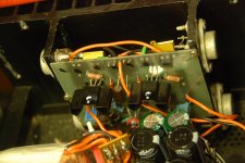
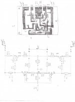
I made my boards the old fashion way, I drew the circuit with a marker and washed it in an acid bath.
Sense the MOSFETs are off the board, I made solder connections for them. I am sure the outputs are wired per the drawing.
I have checked and recheck the board and see nothing wrong. Both channels act the same, so I am pretty sure I have miss-wired or laid something out wrong.
There has NOT been any smoke released thus far!
If this were tubes, I'd pull a few and make sure it wasn't the tubes. These little buggers are harder to get at and easy to smoke.
Attachments
Last edited:
Testing of driver board
...
I am rebuilding a DH200. ...There has NOT been any smoke released thus far!
If this were tubes, I'd pull a few and make sure it wasn't the tubes. These little buggers are harder to get at and easy to smoke.
Hi Rush
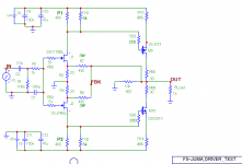
If you want to test your "old fashion" driver board w/o the precious Lateral Mosfet to avoid to fry them, you can test the driver board only by taking the 2 feedback points to the middle of R9/R10 after disconnecting the output Lateral mosfets. Just ensure to test with a higher load (like 1k ohm for example).
See attached sketch example (your resistors values and designations may vary).
Good luck
Fab
Attachments
Last edited:
Juice
Thanks Jacco,
As it turned out the juice was not enough with the GR 170/74s.
I switched to a pair of matched BL at 7.16 idss and everything is biasing up just fine now on the first channel. Yet to try the second channel.
The power supply is around 16.5VDC +/- with one channel biased to .51 Amps each output, (the bias keeps climbing, I keep turning it down.)
And thank you Fab,
I needed to remove the driver board in order to figure this out and I set it up like the schematic you posted.
Everything was wired correctly, just a juice issue!
Positive you have enough of the juice through Q1/Q2 ?
Thanks Jacco,
As it turned out the juice was not enough with the GR 170/74s.
I switched to a pair of matched BL at 7.16 idss and everything is biasing up just fine now on the first channel. Yet to try the second channel.
The power supply is around 16.5VDC +/- with one channel biased to .51 Amps each output, (the bias keeps climbing, I keep turning it down.)
And thank you Fab,
I needed to remove the driver board in order to figure this out and I set it up like the schematic you posted.
Everything was wired correctly, just a juice issue!
Well after some testing I had an oscillation problem, so I inserted a 470pF across the 150 ohm resistors. That took care of the problem.
I also have .040 vdc on the output of the right channel of my QB9 so I added input caps to both channels.
The bias is stable with the cover off, cover on it goes up and everything gets hot! I have the bias set at .5 amp per device with it warmed up, cover off, it sounds great! I may cut some larger cooling holes in the cover, although don't know if enough holes could be cut to make a difference.
Thank you Juma (and Nelson Pass) for a great sounding amp to utilize the chassis and output of the Hafler DH200.
I will post these findings in the DH200 thread also, as that is where this journey started.
Rush
Hi Rush,
I'm glad you made it work
A couple of things to consider:
1. At +/-19V DC PS voltage it doesn't make sense to have such a high bias (0.5A per output MOSFET = 2A per channel) unless you use 4 Ohm speakers. For 8 Ohm speakers you'll stay in class A through whole power range (Vout_max=16V_peak) with 1A bias (250mA per output MOSFET).
2. Make sure to drill enough holes in the amp's bottom and cover plate. Good air circulation helps a lot.
Enjoy your amp
Hi Rush,
A couple of things to consider:
1. At +/-19V DC PS voltage it doesn't make sense to have such a high bias (0.5A per output MOSFET = 2A per channel) unless you use 4 Ohm speakers. For 8 Ohm speakers you'll stay in class A through whole power range (Vout_max=16V_peak) with 1A bias (250mA per output MOSFET)./QUOTE]
But it sounds so good at 2 amps! Who needs a cover?
how high were your standards in 1982 ?
same as today, just couldn't quite make it

basicly because of speaker Xover issues
Xovers were the major problem
ofcourse anything else was blamed
Prettiest and best sounding ones i've heard this year are the AMT140 monaurals from France, Class A up to 3.5 amps out, rather expensive though.
Best bang for the buck are the XA100.5, haven't heard the 160.5 yet.
(valve power amps are out, anything over 75W will do, don't need no power stations. but i fancy balanced, narrows it down a bit)
Best bang for the buck are the XA100.5, haven't heard the 160.5 yet.
(valve power amps are out, anything over 75W will do, don't need no power stations. but i fancy balanced, narrows it down a bit)
- Home
- Amplifiers
- Pass Labs
- F5 meets Buzquito