I bridged today the 47R in the second stage with 1000uF as Lynn suggested to get a kind of no degeneration without thermal runaway.
It works flawless... sound wise I am not yet decided if it is better than with the 47R source resistors alone.
More important the bias of the SK/SJ, I normally go for 1,8V means 40mA. But even here it is worthwhile to experiment. 1.6V deliver a fuller and more fleshy sound.
So here in the second stage more current is not always better, you really have to decide and hear.
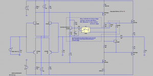
Just in case somebody is interested, here is an idea for a driver bias controller.
Don't mind the bipolar input stage, you can replace it by a jfet stage if you like. I used the bipolar type, because suitable models come already with LTSpice, so it should be easy for everybody to play around with it. Same with the Driver-MOSFETs and the opto couppler.
Although the source degeneration resistor is changed in large steps (factor 10000) , the bias current only changes by about 3%.
Attachments
I bridged today the 47R in the second stage with 1000uF
.
Yeah someone earlier in the thread suggested doing that but I like parts minimisation and simplicity where ever possible, so that's more of a fall back plan.
Just in case somebody is interested, here is an idea for a driver bias controller.
Don't mind the bipolar input stage, you can replace it by a jfet stage if you like. I used the bipolar type, because suitable models come already with LTSpice, so it should be easy for everybody to play around with it. Same with the Driver-MOSFETs and the opto couppler.
Although the source degeneration resistor is changed in large steps (factor 10000) , the bias current only changes by about 3%.
Hi Peter,
That is electrifying!
It is too late now, I will look at it tomorrow!
Danke!
For those searching a circuit that approximates the XA25, I have have some insights.
This might be child's play for Nelson, but to me it verges on torture.
- Limit the bandwidth of the feedback loop in order to achieve a decent phase margin. This can be easily understood by considering that the phase shift per cycle gets worse as the cycle gets shorter. Thus limit how short you let the cycle get. The JFET drain resistance, is a primary parameter controlling the FE bandwidth.
- Minimize the output impedance of the front end to minimize high frequency distortion. The FEOut load resistance is the primary determinant of the FE output impedance.
This might be child's play for Nelson, but to me it verges on torture.
This might be child's play for Nelson, but to me it verges on torture.
Indeed. I was all set to order parts and try to find time to build as of a couple weeks ago, before the gain/phase margin discussion, but I learned my circuit may be unstable. I just "optimized" the output impedance of the front-end a bit more by varying the cascode local feedback and load resistor, but my circuit still has poor gain and phase margins.
Perhaps using GR grade JFETs to allow higher drain resistances would be a good idea?
Look at how the phase margin correlates with the feedback loop bandwidth. If you can keep that bandwidth down around 800kHz, the phase margin will be good, and 800kHz is sufficient BW for a 100V/us slew-rate.
This might be child's play for Nelson, but to me it verges on torture.
Best way to learn.
You certainly won't forget.
Hahaha
Just in case somebody is interested, here is an idea for a driver bias controller.
Don't mind the bipolar input stage, you can replace it by a jfet stage if you like. I used the bipolar type, because suitable models come already with LTSpice, so it should be easy for everybody to play around with it. Same with the Driver-MOSFETs and the opto couppler.
Although the source degeneration resistor is changed in large steps (factor 10000) , the bias current only changes by about 3%.
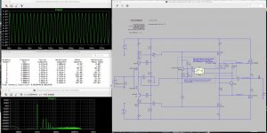
I just followed the trip PR showed in this post.....and put "our" front in (PR helped) and the IXYS we use.... and results look good.
See the low distortion with only 45mA for second stage and 1A5 for the IXYS.
This is of course the result that k2 is first time lower or on same level as k3.
When you run pr simulation you see that the currents in second and third stage are really stable with this idea.
More LTSpice fun!
Thanks Peter!
Attachments
.......
This is of course the result that k2 is first time lower or on same level as k3.
.......
is that what you (we) want ?
as approach more than interesting , however not CFA FE anymore , at least as I see it
I admit my often ambivalence ....... not just interested to figure how things can be done , but usually more interested to figure out how Mithrandir done it
probably just because of usual twist (or two)
I admit my often ambivalence ....... not just interested to figure how things can be done , but usually more interested to figure out how Mithrandir done it
probably just because of usual twist (or two)
Last edited:
is that what you (we) want ?
This is only Spice, who knows what real distortion spectra is.....

This is only Spice, who knows what real distortion spectra is.....
Since you're already in a position to do it, see if you can start comparing what you hear with your distortion analyzer.
I'm a little bit behind schedule, probably have the cases finished by next weekend, then another 2 weeks after that before the amp is complete and ready for testing.
Last edited:
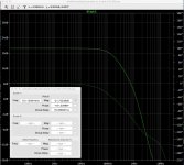
Hi Lynn, can you please help.... when I give in your commands
.measure ac F3db when mag(V(out))=MagVout/sqrt(2) fall=1
.measure ac phase_margin find atan(im(V(out))/re(v(out))) when mag(V(out))=1
.measure ac gain_margin find -20*log10(mag(V(out))) when atan(im(V(out))/re(v(out)))=0 fall=1
I get this
Measurement "f3db" FAIL'ed
phase_margin: atan(im(v(out))/re(v(out)))=(33.7472dB,0°) at 1.75667e+06
gain_margin: -20*log10(mag(v(out)))=(26.0499dB,180°) at 33.9781
- Home
- Amplifiers
- Pass Labs
- F4 Beast Builders