Indeed Lynn the first data had considerable CFB, now with out only global FB
input AC
magvout: mag(v(out))=(21.1412dB,0°) at 1000
f3db: mag(v(out))=magvout/sqrt(2) AT 188336
phase_margin: atan(im(v(out))/re(v(out)))=(33.6045dB,0°) at 1.76034e+06
gain_margin: -20*log10(mag(v(out)))=(26.3862dB,0°) at 1.04495e+07
feedback loop AC
magvout: mag(v(out))=(21.1507dB,0°) at 1000
f3db: mag(v(out))=magvout/sqrt(2) AT 187676
phase_margin: atan(im(v(out))/re(v(out)))=(35.353dB,0°) at 1.81407e+06
gain_margin: -20*log10(mag(v(out)))=(27.3796dB,0°) at 1.42083e+07
both -3dB are very similar
I am still surprised how similar the two set of measurements are, and the gain margin is much higher that I would expect. What is the value of the JFET gate stopper resistor?
the value of the JFet gate stoppers is now 4k7.
input:
magvout: mag(v(out))=(20.0676dB,0°) at 1000
f3db: mag(v(out))=magvout/sqrt(2) AT 208923
phase_margin: atan(im(v(out))/re(v(out)))=(11.3061dB,180°) at 1.19347e+06
gain_margin: -20*log10(mag(v(out)))=(-0.371842dB,180°) at 1.14072e+06
feedback loop:
magvout: mag(v(out))=(20.0771dB,0°) at 1000
f3db: mag(v(out))=magvout/sqrt(2) AT 218373
phase_margin: atan(im(v(out))/re(v(out)))=(33.5678dB,0°) at 1.5334e+06
gain_margin: -20*log10(mag(v(out)))=(29.531dB,0°) at 1.68804e+07
Gerd: I still do not understand why the -3dB frequency for the feeedback loop is so low. Can you show me the Bode plots for the 4k7 gate stopper case and part of the schematic for the feedback loop AC stimulus?
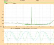
About the best I have been able to do is shown below. Step 1 is for the AC(Input) and step 2 is for AC(FBloop). In order to lower the FBloop bandwidth I increased the values of the resistors in the feedback network
Measurement: f3db
step mag(v(out))=magvout/sqrt(2)
1 137679
2 741667
Measurement: phase_margin
step atan(im(v(out))/re(v(out))) at
1 (24.5328,0) 899345
2 (44.2441,0) 4.64079e+006
Measurement: gain_margin
step -20*log10(mag(v(out))) at
1 (5.88911,0) 1.33251e+006
2 (9.21759,0) 9.65351e+006
You already got mail with .asc file some time ago!
Maybe i make some dummie faults.....:--)€
The only .asc files from you that I can find are in Stabilität.zip, which contains about 15 .asc files. I do not see any voltage sources with AC specifications.
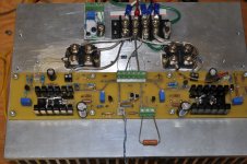
I finally started bench testing.
The initial OS bias circuits caused the output fet bias current to increase from 1.5A at 22C to 1.7A at 53C. A minor change to a resistor in each bias circuit fixed that, and the bias variation is now less than 40mA.
At this point the only tuning has been to tame the H2 level with a 510K resistor on the -rail cascode feedback. I lot of tuning is still required as can be seen in the power and frequency sweeps shown below. The high distortion levels at 25W are probably due to limitations of my bench power supplies. I haven't yet built the final power supply.
Attachments
The high distortion levels at 25W are probably due to limitations of my bench power supplies.
What is power supply voltage used for this measurements?
For XA25 published thd graphs I think that at least +/-30V is needed... or more.
My measurements were made with (slightly less than) 25V rails. I made measurements with 28V rails and the 25Watt distortion measurements fit smoothly with the curves from the lower wattage measurements.
In retrospect, the high distortion levels are due the Vds being less than 7V-8V and the high Ciss and Crrs levels at low Vds values.
The distortion vs. Watts graphs in the Pass Labs XA25 Owners Manual certainly suggests that rail voltages are high enough to stay out of that Vds region, BUT, those plots do not specify the test frequency. If the test frequency is low enough, then Ciss and Crss have a smaller role in the distortion.
Does anyone have a good idea of the efficiency of linear power supplies like those used in FirstWatt amplifiers? By efficiency I mean:
idle power to amplifier (rail voltages * current)
-------------------------------------------------------------------------------
total power from mains
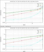
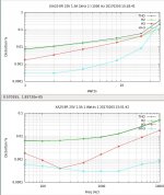
For comparison here are distortion vs. watts sweeps for 25V rails and 28V rails.
From 20w and up there is clear improvement.
2nd harmonic you can tweak to low value, but 3rd is higher then original, IMHO more feedback and/or more bias is needed. (with so low thd original probably have nuled 2nd)
I guess that disipation in power supply is on 15w level (transformer and rectifier heating). With +/-30V and 1.9A bias, there is 228w PD.
More less fitting to the 240w, specified consumption.
Does anyone have a good idea of the efficiency of linear power supplies like those used in FirstWatt amplifiers? By efficiency I mean:
idle power to amplifier (rail voltages * current)
-------------------------------------------------------------------------------
total power from mains
2 channels of F5 is around 120W to 125W/180W, so between 65% and 70%
Last edited:
So we have a fairly wide range of power supply efficiency estimates. Here is the problem: We have a 240W power budget at the mains, power requirements for the front-end (FE), and the output-stage (OS). What rail voltage and OS bias current can we support with a realistic power supply efficiency? I initially went to the low side of 25V for the rails in order to have higher bias current, but 28V rails look a lot better.
If you think about it, why even limit ourselves to those specs.So we have a fairly wide range of power supply efficiency estimates. Here is the problem: We have a 240W power budget at the mains, power requirements for the front-end (FE), and the output-stage (OS).
This is DIY, build it any way you like, if you have adequate sinking you could do 30V rails and 2A bias.
No need to limit ourself here.
Probably wouldn't have made sense for Pass Labs to go higher in power with this amp as it would start to directly compete with their other products, this amp fills a hole in their product line up.
We don't have a product line up or a marketing department to be concerned about.
So we have a fairly wide range of power supply efficiency estimates. Here is the problem: We have a 240W power budget at the mains, power requirements for the front-end (FE), and the output-stage (OS). What rail voltage and OS bias current can we support with a realistic power supply efficiency? I initially went to the low side of 25V for the rails in order to have higher bias current, but 28V rails look a lot better.
Interesting data is :
"Class A envelope: 50 Watt peak for 2, 4 or 8 ohm load"
I think that worst case is 2ohms 50W peak. If I didnt screw up the math, that
is 5A peak in class A. If somehow you can find value of class A envelope, than you can set bias on that value wich giving 5A in class A and rest is free for power supply voltage.
Also would be interesting to do THD vs Power supply sweep, to see, is there load line sweet spot in region 25-35v.
From your thd graphs for 28V rail, can be seen that also higher order distortion is improved on lower power, with higher rails. That can be most important.
I think that worst case is 2ohms 50W peak. If I didnt screw up the math, that
is 5A peak in class A. If somehow you can find value of class A envelope, than you can set bias on that value wich giving 5A in class A and rest is free for power supply voltage.
I think we should be able to get that kind of current output using 2A bias because of the lack of source resistors. Possibly even less, like 1.5A bias.
What was the deal with the square-law effect? You can (theoretically) get up to four times the bias current? Although, in practice, it is closer to three?
- Home
- Amplifiers
- Pass Labs
- F4 Beast Builders