

as I see it , nothing wrong in proper idolatry ....

Did you see this.... is it proper.....
http://www.diyaudio.com/forums/pass-labs/300233-f4-beast-builders-70.html#post4982998
Well you might not want to see that circuit Generg because I cheated. I don't have and idea for the first stage yet so I used an opa2694 with feed back for a voltage gain of 10. But I wonder if it will also have low distortion with a discrete first stage.
Yes I saw that post. You tried to have a little fun and you ran out of smiles. It inspired me to make my ill fated attempt, but still it was fun.
Yes I saw that post. You tried to have a little fun and you ran out of smiles. It inspired me to make my ill fated attempt, but still it was fun.
Take the input part from pr here....
http://www.diyaudio.com/forums/pass-labs/300233-f4-beast-builders-63.html#post4971405
http://www.diyaudio.com/forums/pass-labs/300233-f4-beast-builders-63.html#post4971405
Gerd: I have some issues with the PR front end. The problem is that the rails have to be considerably higher in order to get enough voltage swing from the front-end output to drive output stage at 20V. With the capacitor coupled interface between the front-end and the output stage you get a boot-strapping effect so that the output-stage gates have the full swing of the FE output.
Nice that you occupy with pr´s frontend....
Yes we know this. Is it possible to add the bootstrapping to this circuit or choosing simply a higher PSU voltage to get the 20V swing we need?
And we added two 10k to ground at the drain outputs of the SK/SJ to get more stabilization to possible current changes.
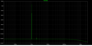
And did you remark that this circuit is per se k3 dominant..... ha, ha!
And when you want k2 dominance put some source resistors in the second stage and there is k2.
Amused I tried the same with the Sony II front end and there was always k2 dominance with and without source resistors in the second stage.
Nice isn't it!
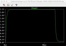
And pr showed me the way to make a rectangle test with Spice for the circuit with a 1uF cap at the output and with the combination 1k gain resistor and 10k feedback resistor for 20dB the result looks like this.....
Yes we know this. Is it possible to add the bootstrapping to this circuit or choosing simply a higher PSU voltage to get the 20V swing we need?
And we added two 10k to ground at the drain outputs of the SK/SJ to get more stabilization to possible current changes.
And did you remark that this circuit is per se k3 dominant..... ha, ha!
And when you want k2 dominance put some source resistors in the second stage and there is k2.
Amused I tried the same with the Sony II front end and there was always k2 dominance with and without source resistors in the second stage.
Nice isn't it!
And pr showed me the way to make a rectangle test with Spice for the circuit with a 1uF cap at the output and with the combination 1k gain resistor and 10k feedback resistor for 20dB the result looks like this.....
Attachments
Is it OK to use such high values of resistors in the global feedback loop? I was under the impression that one should keep feedback resistor values low in a current feedback amplifier.
EDIT: the 1k and 10k, I mean. Standard values from the Sony VFET2 are ~100 and 750.
EDIT: the 1k and 10k, I mean. Standard values from the Sony VFET2 are ~100 and 750.
Last edited:
Is it OK to use such high values of resistors in the global feedback loop? I was under the impression that one should keep feedback resistor values low in a current feedback amplifier.
EDIT: the 1k and 10k, I mean. Standard values from the Sony VFET2 are ~100 and 750.
Run some simulations and look at the Bode plot with the AC stimulus in the feedback loop. You will see that the -3dB frequency increases as the feedback resistors are lowered. Also be sure to look at the phase and gain margins vs. the feedback loop impedance.
Run some simulations and look at the Bode plot with the AC stimulus in the feedback loop. You will see that the -3dB frequency increases as the feedback resistors are lowered. Also be sure to look at the phase and gain margins vs. the feedback loop impedance.
Yes, I ran a couple simulations earlier and noticed improved phase and gain margins. Will have to adjust local feedback levels, or I won't have enough overall gain.
I just seemed to recall something about needing low resistor values for current feedback amps, but don't remember why... Maybe it was from working with high-bandwidth opamps...
Last edited:
I have been making more tweaks and measurements of the one channel I have built. I am beginning to believe that careful matching of the J74/K170 JFETs, J313/K2013 MOSFETs, and IXYS hocky-pucks is required to obtain the distortion plots that are shown in the XA25 User Manual. Measurements of H3 and higher look pretty good, but I haven't yet been able to enough H2 to get very close the the levels shown in those plots. How many of us have a stockpile of NOS JFETs and MOSFETs and can afford to purchase sufficient quantities of the hocky-pucks to do matching? Nelson continues to find ways to screw the cloners.
- Home
- Amplifiers
- Pass Labs
- F4 Beast Builders