You do not. Use only the phase and gain margins measured inside the feedback loop, and measure bandwitdh (-3dB point) from the input.and how do we bring the two results analytically together?
The second Bode plot is the same amplifier but measuring the feedback loop response.
I suspected you would do that.
You will need to build to confirm.
There are too many parasitics to be certain either way.
I'll let you guys grow extra grey hair. Hahaha
When I'm finished with my build I'll be happy to help out more, assuming you still want it
no good luck, my hairs are already grey......

maybe I will loose them when I hear your amp! When you turn a bit louder at Brisbane.....
Last edited:
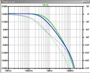
Here are some interesting simulation results. I have been trying to understand why the phase and gain margins of the feedback loop response are so crummy. These plots provide some clues.
In all of the plots, the green tracks are with cascode transistors, and the blue plots are without. In all cases there is no local feedback. Vrail=25V, Output FET bias=1.5A. The FE output load is 270R.
In the first plot the FE MOSFETs are biased at 100mA, with 22R DC-degeneration resistors, and has an OLG of 35dB.
The phase and gain margins are: with cascodes, 38deg and 7.6dB. Without cascodes 68deg abd 15dB.
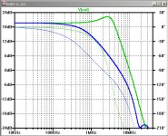
In the second plot the FE MOSFETs are biased at 50mA, with no DC-degeneration resistors, and has an OLG of 50dB. The phase and gain margins are: with cascodes, -69deg and -13dB. Without cascodes 53deg and 9.6dB.
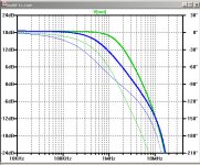
In the third plot the FE MOSFETs are biased at 50mA, with no DC-degeneration resistors, and has an OLG of 35dB. The phase and gain margins are: with cascodes, -1deg and 0dB. Without cascodes 66deg and 13dB.
Bottom line: The cascode transistors increase loop stability problems.
In all of the plots, the green tracks are with cascode transistors, and the blue plots are without. In all cases there is no local feedback. Vrail=25V, Output FET bias=1.5A. The FE output load is 270R.
In the first plot the FE MOSFETs are biased at 100mA, with 22R DC-degeneration resistors, and has an OLG of 35dB.
The phase and gain margins are: with cascodes, 38deg and 7.6dB. Without cascodes 68deg abd 15dB.
In the second plot the FE MOSFETs are biased at 50mA, with no DC-degeneration resistors, and has an OLG of 50dB. The phase and gain margins are: with cascodes, -69deg and -13dB. Without cascodes 53deg and 9.6dB.
In the third plot the FE MOSFETs are biased at 50mA, with no DC-degeneration resistors, and has an OLG of 35dB. The phase and gain margins are: with cascodes, -1deg and 0dB. Without cascodes 66deg and 13dB.
Bottom line: The cascode transistors increase loop stability problems.
Attachments
You always mean the cascode transistors of the j-Fets?
If yes, very astonishing!
Yes, the cascodes of the JFETs.
Nelson has mentioned in the past that there were downsides to using the cascodes, but I cannot find any details about problems and how they were resolved. Clearly, the XA.8 line of amps use them.
In that previous post #588, that was a comparison of no-cascode vs cascode with no local feedback. I need to try some comparisons with no-cascode vs. cascode with LFB, where to global feedback is the same and other parameters are the same.
I am guessing that a major effect of the cascodes is to eliminate the Miller capacitance of the JFETs, thus vastly speeding up the input stage. This results in significantly higher open-loop bandwidth and allows the other capacitances (primarily the MOSFETs) to become dominate in determining the phase and gain margins.
Flapping Tails
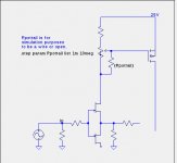
Here are some more interesting plots. Did you ever question whether to short the wiper to the end of the bais pot toward the JFET? When left open, I refer to this as a "flapping tail". How can that be significant your say. Mr. Miller steps in to collect his toll - bandwidth. The larger the resistance of that tail, the more delta-v on the drain of a JFET without a cascode, or on the collector of the cascode. This lowers the bandwidth of the input stage.
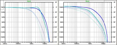
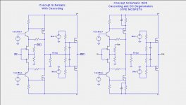
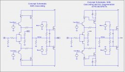
In the plots below, we have a simplified schematic of the circuit, and the feedback-loop Bode plots for a cascoded and non-cascoded stages. Each of the Bode plot contain Blue traces for the non-flapping tail and the Cyan traces for the flapping tail. In all cases the pot was 1K and the tail resistance was 675R.
Takeaway: If you want to maximize bandwidth, eliminate the tail. If you want lower the bandwidth, add more tail resistance. Changing the bandwidth in the feedback-loop also changes slew-rate.
Here are some more interesting plots. Did you ever question whether to short the wiper to the end of the bais pot toward the JFET? When left open, I refer to this as a "flapping tail". How can that be significant your say. Mr. Miller steps in to collect his toll - bandwidth. The larger the resistance of that tail, the more delta-v on the drain of a JFET without a cascode, or on the collector of the cascode. This lowers the bandwidth of the input stage.
In the plots below, we have a simplified schematic of the circuit, and the feedback-loop Bode plots for a cascoded and non-cascoded stages. Each of the Bode plot contain Blue traces for the non-flapping tail and the Cyan traces for the flapping tail. In all cases the pot was 1K and the tail resistance was 675R.
Takeaway: If you want to maximize bandwidth, eliminate the tail. If you want lower the bandwidth, add more tail resistance. Changing the bandwidth in the feedback-loop also changes slew-rate.
Attachments
Not really new, only searching. But there are cascodes in the XA circuit, ehere?
Besides this, your research is very useful Lynn!
AdvantagesEdit
The cascode arrangement offers high gain, high bandwidth, high slew rate, high stability, and high input impedance. The parts count is very low for a two-transistor circuit.
DisadvantagesEdit
The cascode circuit requires two transistors and requires a relatively high supply voltage. For the two-FET cascode, both transistors must be biased with ample VDS in operation, imposing a lower limit on the supply voltage.
"The cascode arrangement offers high gain, high bandwidth, high slew rate, high stability, and high input impedance. The parts count is very low for a two-transistor circuit."
Is this a quote from somewhere? I am wondering if you have to remove "high stability" from the list. When it is used to significantly increase the bandwidth, phase-lag from the the output stage and other circuit elements dominate and give rise to the possibility of oscillation.
Another benefit of cascoding the input JFETs: Allows the rail voltages to increase beyond the rated Vds limits of the JFETs.
I have an example of the cascoded circuit where the FB loop phase margin is good. I am playing around with it to see how it can be further optimized.
I have an example of the cascoded circuit where the FB loop phase margin is good. I am playing around with it to see how it can be further optimized.
Juan from Spain is just too building an F4 beast and he used one of "my" circuits. And he run into some problems due to my not full description what I did.
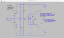
So here again a circuit running just now at my home with no sign of oscillation, as a possible starting point.
Only 50mA for the Toshibas, still degeneration 33R in second stage, no cascode feedback. So the distortion values are higher around 0.01% at 1W/8.
I am still varying this circuit, so more is to come...... :--) and of course also from 2picodumbs and Lynn!
Some of the circuits I showed are only simulations, LTSpice ghosts.... !
:--))
and I do not know if they have the phase and gain margin necessary. 2picdumbs and Lynn can handle this hopefully much more better.
So my running circuit with some more hints.
I recommend before connecting the FB resistor and the frontend output to the output stage, adjust the offset of the output stage alone first as good as you can.
Otherwise this offset goes over the feedback resistor to the frontend and can cause a bigger mismatch between the offset at the pre output and the output output.
So here the circuit.....
Attachments
- Home
- Amplifiers
- Pass Labs
- F4 Beast Builders