PMA said:
Michael,
sure. Sorry for small delay, but I decided to prepare a new graph with standard feedback terminology included. Here it is, and I am sorry for my pencil-drawn graph shown before.
The graph attached shows contribution of the feedback capacitor as well.
Pavel.
Hi Pavel,
what is the green line (1/beta) in the upper plot and how does it correlate to the other lines?
Have you measured how the amplifier behaves without Cfb, would be interesting to see how gain and phase changes.
While you eventually would perfom another gain/phase measurement it would be interesting to know how gain/phase look like with the "old" Cfb (was it 22pF?), so we can verify the oscillation to it (as I think you made a "hit-n'-miss" test with the Cfb)!
Cheers Michael
Beta is feedback factor, 1/beta is inverse of feedback divider (with Cf cap), close to closed loop gain.
Notice that intersection of 1/beta curve and open loop gain curve (amplitudes) are at the same frequency as loop gain = 0 dB.
Loop gain (Aol * beta, the middle amplitude curve) is crucial for stability. At intersection of loop gain with 0 dB (1.43MHz) look at loop gain phase char. You will see the stability margin, which is 55.4°. Stability margin is 180° - 124.6° (phase angle at 1.43MHz). If the phase angle was 180° instead of those 124.6°, phase margin would be 0° and amplifier would oscillate.
MikeB said:Thanks for the bodeplot Pavel. Is this for the 220pf+3.3pf ?
Mike
Yes, it is. But calculated by simulation SW, and as I use 2 different versions, both give a little bit different results.
Anyway it seems to fit with real circuit quite well, and it explains the role of small feedback capacitor. I can easily simulate oscillation conditions, if I increase the feedback cap to 30pF and more.
PMA said:Beta is feedback factor, 1/beta is inverse of feedback divider (with Cf cap), close to closed loop gain.
Hi Pavel,
of course, thank's for explaining the obvious I missed to see!
")
Cheers Michael
Exciting !
Onsemi has new powerdevices:
http://www.onsemi.com/PowerSolutions/product.do?id=MJL0281A
The specs sound promising ! Samples not available yet...
Mike
Onsemi has new powerdevices:
http://www.onsemi.com/PowerSolutions/product.do?id=MJL0281A
The specs sound promising ! Samples not available yet...
Mike
If you have a split secondary I'd use two separate bridges one for the plus and one for the - voltage. The bridges of course would be made up using discrete schottky diodes.
So a total of 16 diodes for quad secondaries (or two xform) for a stereo.
MikeB
Although ex motorola makes decent clones I'll stick to the japanese originals. They're FAR superior IMHO.
So a total of 16 diodes for quad secondaries (or two xform) for a stereo.
MikeB
Although ex motorola makes decent clones I'll stick to the japanese originals. They're FAR superior IMHO.
Thanks folks, but now I'm a bit puzzled. My questions right now are:
a) Is there a measurable advantage like lower noise of Schottky diodes or soft recovery types over standard rectifier diodes and integrated bridges?
b) What are the advantages of split bridges for + and - rails, and
c) what are the pros of split bridges for each channel?
a) Is there a measurable advantage like lower noise of Schottky diodes or soft recovery types over standard rectifier diodes and integrated bridges?
b) What are the advantages of split bridges for + and - rails, and
c) what are the pros of split bridges for each channel?
Lukas, these 1ohm resistors, skip them ! For example, if you have a peak into 4 ohms of 32v, you get already 8 amperes, multiplied by the "timefactor" the diodes are open, you easily loose more than 10volts. This easily halfes the outputpower and might destroy all dynamics in low frequencies. Would be a pity.
Symasym was designed to have reasonably high PSRR, it should not need these. I tried some snubbers, but heard no difference.
About the MURs, may i suggest MUR820 instead of MUR860 ? 200v rating should fit and MUR820 is ~2 times faster.
If you already have 2 metal bridges, use these, they have typically a rating of 25a/250v and are not bad and "undestructable".
Go, and use the 2 metal bridge rectifiers, one per channel (like Chris already said), also one capacitor bank per channel. I suggest 2x ~10000uf per channel. I use 2x22000uf (BC caps) for a single psu for both channels, seems to be enough. Bigger caps can do more harm then they help. (worse ESR, torturing the diodes)
I have not investigated PSUs very much, made some simulations to investigate the diode ringing, unless you know exactly what you are doing, do not place any caps across diodes or in paralell with the ac-supply, you risk turning the ringing into oscillation. A nice RC on primary side can really help, but needs suitable parts and can be installed afterwards.
If you look at Pavels measurements, the 100hz ripple is barely visible (< -110dB), and if i remember correct, Pavel uses a "normal" PSU. Pavel can you show what you exactly used as PSU ?
Grataku, i will try to compare these onsemi devices...
Mike
12 Cents said:Thanks folks, but now I'm a bit puzzled. My questions right now are:
a) Is there a measurable advantage like lower noise of Schottky diodes or soft recovery types over standard rectifier diodes and integrated bridges?
b) What are the advantages of split bridges for + and - rails, and
c) what are the pros of split bridges for each channel?
About a), it's the ringing creating HF-trash into the rectified voltage, b) i am not convinved that it is really better, except it halfes the load to the diodes, c) better separation of the supplyvoltages, giving better stereo separation.
b) might get interesting when you make a dual bridge per channel, creating extra power grounds per channels.
Pavel, i hope you do not refer to my open air wild construction...
"My hair are getting up with fear", do you have a photo of that ?
Mike
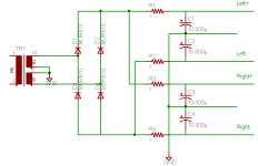
Correctly designed amp have without problem SNR over 120 dB ( IHF-A ) or over 115 db linear and is free, if there are " normal " rectifier or some with " soft knee ". But I say again, correctly designed... . If isn't, any " exotic " diode can help... Mike, today I was by Pavel, listen your " baby " - I must say, that it is very good amp and have sound, which I like... Is very transparent, have good drive and is very clear... Congratulation !
. If isn't, any " exotic " diode can help... Mike, today I was by Pavel, listen your " baby " - I must say, that it is very good amp and have sound, which I like... Is very transparent, have good drive and is very clear... Congratulation ! The PSU is much like this, with 100nF caps in parallel with electrolytes.
The diode bridges are rated at 15A.
/Thank you RodE, I borrowed the picture a little bit, as I was lazy to draw a new one, always friends /
The 10R resistors between IGND and PWGND of Symasym help to prevent ground-loops a lot.
The diode bridges are rated at 15A.
/Thank you RodE, I borrowed the picture a little bit, as I was lazy to draw a new one, always friends
/The 10R resistors between IGND and PWGND of Symasym help to prevent ground-loops a lot.
Attachments
- Home
- Amplifiers
- Solid State
- Explendid amplifier designed by Michael Bittner, our MikeB