Dear Hugh,
I have respectfully read your standpoint and I have absolutely no need to dispute with you.
Probably if you ever read my thoughts about influence of HF interference, D/A residuals etc. you would not call me an iconoclast.
But it is your attitude and why should I quarrel about?
Yours faithfully,
Pavel Macura
Toshiba drivers are nice, the plastic ones are wonderfull.
I made some experiences,and sounded a bit better than MJ340/350.
Well guys....Symassym sounds good the way you construct it...only severe bad luck will turn you deceptive.
The amplifier is reliable, well designed, deeply tested, revised, ugraded, updated, tweeked, misadjusted, underbiased, overbiased, with good supply, bad supply, with good speaker, bad speaker.
The only way it has to sound bad is if you make some cuts in your speaker.... introduce sand inside the gap of give a kick directly in the middle of the voice coil.
Can be bad too if you crash your car (bad mood)...if your mother in law decide to go to leave with you (tragedy)...if your wife decided to change you by someone more young or if you install a high distorted portable radio...with low voltage batteries....and insert all volume in the Symassym input.
Also, be attention if you have not a small dark cloud following you at all time long...raining over you and never touching others...if you use to cut yourself when shaving each morning...if your tires use to be flatten, your new car explode the motor or exaust the brand new battery...or the only bird that use to fly over your town.... made something that crashes directly over your head...hehe....bad luck maybe.
Other sittuations...do not worry and be happy!...if not sounded good....change parts, check parts, if continue to sound bad...change input source...continuing to sound bad...sorry man...nobody told ya....but i have some small suspections that there are a small possibility that you have listening problems.
Icnoclastic was interesting Hugh, very subtle information.....was deep that...i had to search hystory book.... well, well.
regards,
Carlos
HI Carlos,
yes, the plastic toshiba is what I have, to save me a trip to the basement, do you remember what you used?
the sanken are the 2922 and whatever the pnp is.
I believe in the amp, but I believe the pcb can use some work.
I really have no clue about pcb design and I don't have distrortion measurement gear to help me in the decision making.
I have heard about putting in a gnd plane and other things but I had mixed results with gnd planes.
I think we can all agree that a pcb that gives lower distortion on the same exact design would sound better (unless all the distortion turns into 5th or higher harmonic).
Grataku, Sanken sc2922/sa1216 are the ones Carlos uses, so your outputstage would be identical to his. The PCB needs some work with the powergnd, i have no clue how the sound will change. Like Pavel said, a puzzle. As the distortions are mostly even order, there is the danger that they did "improve" sound, but i hope not.
Mike
Mike
Re: An image especially for mikeks
Image of what...?
PMA said:Hi Michael_K,
I have prepared one image especially for you")
Pavel
Image of what...?
12 Cents said:dx master, you wrote that you have done a matching tool, can you show that to me? Right now I only have this:
Please look at the PDF.
This is what build and now will sit in a box with a Gosse DMM.
The PNP Testpart ist eq. to the NPN Testpart !
And resolved over a 'Umschalter'.
Attachments
Or for just matching some small signal bjts a much simpler version... (see attachment)
You only need one of these constructions, it's identical for npn and pnp.
I used a dip8-socket for placing the transistors, the whole thing fed by a 9v battery.
The vbe is simply measured by checking the voltage between base and emitter, the hfe is calculated by simple math:
Re = one of the 1k at emitter side
hfe = V(Re)*100/V(R3)
V(Rx) = voltage across resistor. Not the perfect accurate one, but built quickly.
Mike
Attachments
Grataku was answered by direct mail...well guys!
Always Germans..... always!
You have special intelligence in my point of view, because i had many examples...i will start to eat those vegetables...Krau....something alike, to have that acid fosfóricum, or some bissulfitum intelectualibus...something to make me more clever.
Many monthes without understand a lot of things that Bittner explained me...as he is thousand years advanced related me!...there are posts that seems Japanese, and i know to read some words in Japanese, and they seem easier to me.
Well...there are people that have better school, better education and maybe some faster intelligence, better memory or something alike that......well...i can feel Germans very clever.
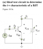
The Bias circuit is clever, really smart, as you can decide the real voltage and the real current, to test your gain with the current and voltage the circuit will need...so...measurement will be better, more realistic, and more precise.
Yeah!...Germans....very good...i will have another sausage...maybe i can turn more clever.
Zier gut!
Carlos
Always Germans..... always!
You have special intelligence in my point of view, because i had many examples...i will start to eat those vegetables...Krau....something alike, to have that acid fosfóricum, or some bissulfitum intelectualibus...something to make me more clever.
Many monthes without understand a lot of things that Bittner explained me...as he is thousand years advanced related me!...there are posts that seems Japanese, and i know to read some words in Japanese, and they seem easier to me.
Well...there are people that have better school, better education and maybe some faster intelligence, better memory or something alike that......well...i can feel Germans very clever.
The Bias circuit is clever, really smart, as you can decide the real voltage and the real current, to test your gain with the current and voltage the circuit will need...so...measurement will be better, more realistic, and more precise.
Yeah!...Germans....very good...i will have another sausage...maybe i can turn more clever.
Zier gut!
Carlos
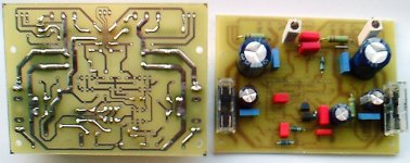
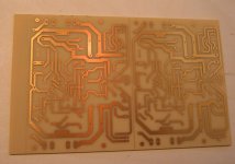
Thanks Mike and Uwe! See attached my board, done with a gutted scanner as glass fixture, some traces have small holes (can be checked well by holding against a 100W light bulb), I will use some solder for that.
Oh destroyerX, Mike is smart, and you are heartful (new word... I mean hearty).
Oh destroyerX, Mike is smart, and you are heartful (new word... I mean hearty).
Attachments
Yes, that worked out. I used 3 min but maybe will up to 4, because it needs to heat up or sth and after 2 min it has maybe 80% maximum light output. I developed ~ 3min. Was not too clever and wiped the board dry with toilet paper after developing and rinsing, that left some resist in some areas where it shouldnt belong. But all in all worked and was fun  . This hobby is so many-sided
. This hobby is so many-sided 
- Home
- Amplifiers
- Solid State
- Explendid amplifier designed by Michael Bittner, our MikeB