12 cents,
no need to change that, my UV-lamp is also such a "Höhensonne" for treating skin. It has 3 IR emitters and one mecurylamp. If i remember correct, these IR-emitters are in series with the uv-lamp, limiting the current. My lamp is from the 70's, guaranteed unhealthy...
It is likely that your lamp is also a mercury-lamp, if yes, you see small bubbles of mercury inside. Don't mess with it !
After mine was on for 2 minutes, it is RED HOT...
Mike
 !
!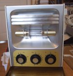
Hi Lukas,
it looks like the filter is adjustable, if moving to zero position it should no longer cover the bulb. Your's is quite similar to mine and is for sure a mercury lamp. Don't mess with it and use this thing as is !
Use it standing, clamp the glass to the pcb and put it "standing" in front of the lamp with ~40cm distance and use the max timing.
Don't underestimate the power of this lamp, never look into it when active. Direct sunlight is poor compared to that !
I overlooked your question about the matching, no complementary matching (except outputstage maybe). Match Q1 <-> Q2 , Q4 & Q12, Q3 & Q9. Match for hfe and vbe, except q3/q9, these need only vbe matching.
Also matching r5/r6 can help.
Matching between channels might be interesting for q8, and r29/30.
Ah, and yes, i reuse my NaOH.
Mike
darkfenriz said:"Sound" sometimes means just "OK" "correct", like "save and sound" and I guess Sheldon meant this
Yes, an example of a word in English with several possible meanings that are defined by context. Makes the language flexible, but also confusing, especially for non-native speakers. It's easy for us native speakers to forget that.
PMA said:Thank you, you are right, I got it. This makes sense. Thanks for explanation and I apologize to Sheldon.
As our Aussie and Kiwi friends would say: No worries Mate.
Sheldon
Sheldon said:
As our Aussie and Kiwi friends would say: No worries Mate.
Sheldon
Thanx!
Shoulda known better ....
I made a very good film with an Epson Stylus Color 670 and a quite expensive inkjet film. Setting "Photo Quality glossy film". Printed two times, this printer is really accurate. I have not the type of the film now, because I only bought two sheets, but I will go back and look. No-name cheapo ink.
I dont want to disturb, maybe more people are waiting for a pcb group buy, but this is getting fun !
!
I dont want to disturb, maybe more people are waiting for a pcb group buy, but this is getting fun
!Re: 2SA1695/2SC4468
Dear Pavel,
many thanks for your comments !
But the MJL will arrive an Dezember 2005 and i will test/ hear the amp !
Then i will disconnect these 2SA1695/2SC4468 and replace it with the MJL...
Alternativ i have 2 pair of 2SC2526/ 2SA1076 from Fairchild.
Datasheets from 2SC2526/ 2SA1076 Fairchild
Dear Pavel,
many thanks for your comments !
But the MJL will arrive an Dezember 2005 and i will test/ hear the amp !
Then i will disconnect these 2SA1695/2SC4468 and replace it with the MJL...
Alternativ i have 2 pair of 2SC2526/ 2SA1076 from Fairchild.
Datasheets from 2SC2526/ 2SA1076 Fairchild
PMA said:Uwe,
these Sanken devices are little bit slower, so there probably should not be the stability problem (probably, should be tested).
But hFE (current gain) of these transistors falls quite quickly with Ic, IMHO the possibilities (parameters) of the symasym will not be fully utilized with these devices.
Pavel
MikeB said:Mikeks, i made bodeplot closedloop because of the effects caused by the 22pf in the feedbacknetwork.
Maybe you forgot to subtract the phaseshift introduced by the inputfilter ? Mike
Hi mike...
Nothing wong with amp. per se...don't get me wrong....
If you look back at my post, it was in response to Pavel's problems with stability....
I did some investigation, and found that the relatively small phase margin may be the cause of the Pavel's problems...
In response to your remarks above, i think you'll find that the closed-loop response is unlikely to yield much info about stability...
Secondly, the input filter does not affect stabilitymargins at all, since it is not in the feedback loop...
Be that as it may, given a robust Thiel network at its output, the amp. should probably be fine with most two-way transducers...
Upupa Epops said:We all don't know your CV, Maestro...
I think you'll find CVs don't design amps....

Incidentally, i have written a simple article on compensation in this very topology....
http://www.diyaudio.com/forums/showthread.php?s=&threadid=63038
Practical loop-gain measurement...
http://www.enel.ucalgary.ca/People/Haslett/Enel647/ReturnRatioStability/MiddleBrook75.pdf
http://www.enel.ucalgary.ca/People/Haslett/Enel647/ReturnRatioStability/MiddleBrook75.pdf
mikeks said:
Secondly, the input filter does not affect stabilitymargins at all, since it is not in the feedback loop...
Exactly that was my point, it adds phaseshift but is not inside feedbackloop, so it's phaseshift needs to be subtracted, assumed that the inputsignal has 0° phase.
According to sims with openloop, the bodeplot gives an oscillation of ~2mhz. Closedloop i get ~10mhz for the 180° shift, much closer to measured one. It's not easy to find the real value, but i am happy with it right now.
Mike
Glúteus maximus is terrible, beeing a philosopher or even a target.
Beeing my dear Mikeks.....ahahahahhaha....against the wall guys...ahahahahha!
This man, Mikeks is incredible related intelligence and Universitary formation, PHD he already colected many, and related to be clever, when we start to study a subject.... the first seconds we start to boil our minds, he already arrive with the solution.
See the image...also the crab is a Philosopher, he is exactly over a "glúteus maximus!"...ahahahahahha!
regards,
Carlos
Attachments

mikeks said:
I did some investigation, and found that the relatively small phase margin may be the cause of the Pavel's problems...
This sounds much better
. And it has been really a delicate game with that Cf, as it always is with the integrator capacitor, provided the amp is not unity gain stable, and this is not ....Make the Cf accurately small and you reduce slope of intersection of CLG and OLG gain curves, possibly resulting in lesser phase angle at this intersection point.
Make the Cf bigger, and you get the power oscillator
PMA said:
Make the Cf accurately small and you reduce slope of intersection of CLG and OLG gain curves, possibly resulting in lesser phase angle at this intersection point.
Make the Cf bigger, and you get the power oscillator
Exactly !

As the oscillationfreq is quite high, sims seem to be correct regarding the lesser phase angle at the intersection point caused by the cf.
So, a correctly dimensioned cf adds stability. (In theory) delicate game...
A too big one will make every not unitygainstable amp oscillate.
Mike
So whas going on with this esplendid amplifier?
Not as esplendid as the girl in Mikekikekikeks avatar.
Has anyone printed out some boards so I can try it?
I'd like to build the amp with different output transistors and drivers. Just because I have some sanken and some to220 toshiba drivers that are looking forward to be put to work.
I read about the guy that swapped the output trannies. I had to do the same thing (lower the feedback cap) to solve the oscillation problem in another amp.
I am wondering if a rethinking of the PCB would be helpful.
grataku said:I am wondering if a rethinking of the PCB would be helpful.
Yep, i have planned that, but will take a while. With the actual PCB symasym still performs very good !
About the Toshiba drivers, i can't guarantee that they work, but Carlos also used some of these.
Mike
Pavel,
I certainly mean no criticism of the amp; I've not heard it. But I know from my own experience that component selection and pcb layout is crucial, and while some of this work is done, there could be more ahead. This is akin to presentation after preparing the meal; I choose this analogy because it is very subjective.
Pavel, I do not make any biting technical points with you. Doubtless you would buy and sell me on these fine issues. I do criticise you for your iconoclastic, elitist engineer stance, however, very sharply. It is humbug, and you need to be told by someone. I have rarely met anyone, however stupid, who did not have one skill or ability superior to my own. But, to your great credit, you have been extremely helpful to everyone who has asked questions, and for that I offer my praise. As we say here, 'Good on ya, cobber, you're a mate!'
Just to make it clearer on your suggestion of competition between our designs; definitively, NO. Your design is open source; mine is proprietary. This is Linux and Windows; you are comparing apples and pears, so this is no competition at all.
Earlier on I alluded to phase lead. I have found that if you reduce lag comp to the verge of instability, then add around 10%, you can then confer monumental stability by adding phase lead from collector of VAS to feedback node, typically 1/3 of the value of the lag comp, but depending on application of course.
This dimensioning can be calculated, and good PSpice is probably a good guide, but the final solution is best achieved by testing with capacitive loads and exhaustive listening tests. Layout plays a big part, obviously. This takes a TRUCKLOAD of time, but when you have it right, the results are extraordinary.
Cheers,
Hugh
- Home
- Amplifiers
- Solid State
- Explendid amplifier designed by Michael Bittner, our MikeB