I'm regretting not purchasing the -S version of my scope with built in waveform generator. It would have been much cheaper than now buying the cheapest Rigol generator. Would this have all the functionality I would need for diyAudio stuff?
I presume the workflow would be to inject at, for example, the point shown in the attached via a BNC-alligator clip cable (or similar). It still seems something of a wayward cause trying to calibrate something which can only display on a small screen and without log frequency axis... I can save the data as a Reference and export that but it is a .ref file and my Mac thinks it is a Unix executable file so I'm not sure I can do anything with it.
(I have a software on my computer which has a signal generator. I guess the issue, however, is getting an accurately known amplitude. DMM?)
Attachments
Last edited:
buy a signal generator. But do check the claimed step response. Some claim quite high frequency, but lowish speed of the step response. sqwave look like Egyptian pyramids with the tops chopped off.
Sinewaves are not clean, both of mine have tiny peaks on the waves that are clearly distortion. A +ve and -ve diff scope trace shows this distortion up and just how bad it can get, particularly when the signal has passed through a filter.
If you need clean, buy a specialised sinewave generator that actually achieves "clean".
The signals generated from digital are limited by the poor step response.
Have a look at a 1kHz sqwave generated by a PC.
Imagine what that might look like for a 10kHz square wave !
Last edited:
Maybe it's possible to open all four DIP switches and inject there, so you're fighting against a weak opponent.
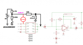
Something like the attached may work. The oscilloscope measures the peak-to-peak voltage, and the frequency, at node A. Then you hold your breath and trust the resistor vendor to give you a perfect 1000-to-1 attenuation at the injection point. (Since your instruments don't work at such teeny amplitudes). Notice that the output impedance of your signal injection network is 10 ohms -- good. Low noise. Check.
BTW here is the signal generator I bought most recently (Amazon link). I like the fact that its square wave output amplitude is adjustable, just like the other waveforms. It's not a cheapo box with a TTL digital chip driving the separate square wave output connector (red flag! separate output connector for square waves) at fixed, unchangeable TTL logic levels.
You could spend a lot less (example) if all you wanted to do was feed 1kHz sinewaves into FFT measurements for amplitude calibration. Not a great long term piece of test gear to be proud of, but an inexpensive short term jury rig.
Attachments
Fairly easy and cheap to assemble a very accurate 9:1 (or 1/10th) Hamon divider...........Then you hold your breath and trust the resistor vendor to give you a perfect 1000-to-1 attenuation ...........
How to Build a Hamon Resistor Divider Network
With care and a lot more time one can assemble a dual, series connected Hamon divider for 1/100th
I have not assembled my three stage Hamon divider yet, but I will when I get time.
http://www.diyaudio.com/forums/equi...rate-0-1x-0-01x-calibrations.html#post2178586
and others.
100r over 10r is not 1/10th it gives 10/110 = 0.090909 repeating.
one needs a 9:1 ratio to get 1/10th
90 over 10r gives 10/(90+10) = 1/10th exactly.
this is the principle of the Hamon divider.
cascading two dividers gives exactly 1/100th
900 over 100 and then 90 over 10 gives the 100 of the first divider as one cascades the two together to get the required 1/100th
adding on a further 9000 over the combined total of 1000 from the previous two stages gives the final 1/1000th.
C.Hoffman has diagrams explaining all in pictures.
Or you just use your 2015 vintage, $35 digital multimeter with 4.5 digits of accuracy, to measure the two resistors Rtop and Rbot. Calculate
Here are two $35 multimeters. One has Non Contact Voltage measurement and 3.5 digits; the other lacks NCV but displays 4.5 digits. Both have autoranging and the feature I sought most urgently: auto shutoff.
- A = Rbot / (Rbot + Rtop)
Here are two $35 multimeters. One has Non Contact Voltage measurement and 3.5 digits; the other lacks NCV but displays 4.5 digits. Both have autoranging and the feature I sought most urgently: auto shutoff.
Thanks Andrew, Mark. I need to think about the signal generator. One advantage of the Rigol is I have someone I can pester easily for info/firmware updates etc. Is the one I linked to good enough?
Re the Quasimodo, I should give this a go since I have one sitting here already. My through hole resistor parts bin isn't as well stocked as you guys have. I do have a 0.1% 47K resistor and a 47R resistor which measures 47.0 with my DMM. So a higher input impedance - too high?
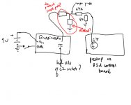
Mark, I don't follow your sketch fully. The output voltage divider is fine. But I'm not clear where the connections to/from the Quasimodo would be made. I don't need the Quasimodo snubber so I think I take the output from the high side socket of C2. Quasimodo schematic attached. I'm confused by the 4.7kR/6mR divider. See attached sketch. I presume I need to protect the scope probe with a series resistor between it and the Quasimodo (your 4.7k). I have 2k, 3k and 8.2k to hand.
EDIT: oops... the 4.7kR/6mR protects scope probe without screwing up the 1/1000th attenuator
Re the Quasimodo, I should give this a go since I have one sitting here already. My through hole resistor parts bin isn't as well stocked as you guys have. I do have a 0.1% 47K resistor and a 47R resistor which measures 47.0 with my DMM. So a higher input impedance - too high?
Mark, I don't follow your sketch fully. The output voltage divider is fine. But I'm not clear where the connections to/from the Quasimodo would be made. I don't need the Quasimodo snubber so I think I take the output from the high side socket of C2. Quasimodo schematic attached. I'm confused by the 4.7kR/6mR divider. See attached sketch. I presume I need to protect the scope probe with a series resistor between it and the Quasimodo (your 4.7k). I have 2k, 3k and 8.2k to hand.
EDIT: oops... the 4.7kR/6mR protects scope probe without screwing up the 1/1000th attenuator
Attachments
Last edited:
Good that you looked at the Quasimodo V4 schematic. Remove Cx, Rs, Cs from their sockets. Use node "drain" as the output when treating Quasimodo as a pulse generator in this scheme. Node "drain" drives two external resistors, Rtop (10K) and Rbot (10R). Or other resistor values as you please. Higher Rbot will give higher thermal noise but maybe it won't be noisy enough to obscure the calibration peak you are injecting. Try it and see!
Look at Figure 2 of the Quasimodo design note, p.3. You will see 4.7K and 0.006R and a switch. The key to understanding everything is this switch. Pause and consider. Ruminate.
It just so happens that this MOSFET's on resistance is 0.006R. Maybe that's a clue.
Look at Figure 2 of the Quasimodo design note, p.3. You will see 4.7K and 0.006R and a switch. The key to understanding everything is this switch. Pause and consider. Ruminate.
It just so happens that this MOSFET's on resistance is 0.006R. Maybe that's a clue.
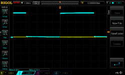
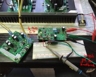
Unfortunately I don't think the Quasimodo setup is going to work. It's a mass of noise. Pic 1 is setup. Pic 2 is upstream of voltage divider. Pic 3 downstream. (Looks like I need a new 9V battery.) (Ignore channel 1 yellow; I never got so far as to connect it to the pre-amp.)
BTW note the overshoot to the downside when the Quasimodo FET turns off.
BTW note the overshoot to the downside when the Quasimodo FET turns off.
Attachments
Then I guess you still have the options (a) read manuals and other resources to figure out how to get "millivolts of noise amplitude" from your FFT traces; (b) use something other than Quasimodo, to feed in a reference.
Since the purpose of calibration is merely to teach yourself how to interpret the scope display, maybe it doesn't have to include the power supply circuit at all? Maybe you can set up the scope on the PSU, dial in the offset setting and the gain setting and wazoo setting and the blortpfaffen setting, then unhook the probes from the PSU and hook them to your little calibrator jig instead?
Now you can build a little doo-dad on your breadboard that includes low current components (for lower dI/dt noise on ground), which makes a known amplitude, 10mV (or 1mV or 100mV, whatever you need) signal at a known frequency. Snap a picture of the FFT output and voila. This many divisions correspond to that many millivolts.
I got ARTA up and running on my Mac and I have a Roland Quad Capture external sound card. (Not as good as an ESI Juli@ but not completely useless. It measures 0.017% THD+N with -3dB points of less than 10Hz and circa 18.5kHz. I normally use it for Room Equalisation Wizard.)
But... In addition to a few questions to diyAudio member Preamp about how to calibrate ARTA properly (I still haven't gotten this properly figured out) I am having a lot of issues with noise. I did a bit of poking around.
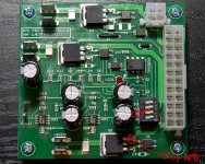
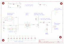
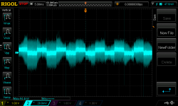
The TPS3510 is in a state such that the pass transistors are turned off. However, I got a big surprise when I looked at the drain pins of the pass transistors with my scope. See attached pic for probe points (using probe GND spring). The second pic is what I get in my scope. (Schematic attached as well.) I presume this is EMI? (There seems to be some residual, 1Vrms, even when I turn the power supply off.) Presumably this, and its harmonics, is getting fed into the pre-amp as well when one of the dip switches is closed...
If it is coupling in via my temporary wires from the regulators, it can make it through an 'off' pass transistor?
But... In addition to a few questions to diyAudio member Preamp about how to calibrate ARTA properly (I still haven't gotten this properly figured out) I am having a lot of issues with noise. I did a bit of poking around.
The TPS3510 is in a state such that the pass transistors are turned off. However, I got a big surprise when I looked at the drain pins of the pass transistors with my scope. See attached pic for probe points (using probe GND spring). The second pic is what I get in my scope. (Schematic attached as well.) I presume this is EMI? (There seems to be some residual, 1Vrms, even when I turn the power supply off.) Presumably this, and its harmonics, is getting fed into the pre-amp as well when one of the dip switches is closed...
If it is coupling in via my temporary wires from the regulators, it can make it through an 'off' pass transistor?
Attachments

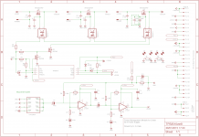
It seems you may have probed the "top" leg of the three legs. The International Rectifier datasheet says that is the Source and not the Drain. Have I misunderstood?I got a big surprise when I looked at the drain pins of the pass transistors with my scope. See attached pic for probe points (using probe GND spring)
Attachments
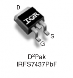
My bad. It was very late and I got my p and n muddled up. Yes, the Source - the low side of the switch.
(I also don't seem to be getting a voltage ratio of circa 49dB when I measure the voltage out of my sound card versus out of the pre-amp but I will test this again at some point today.)
(I also don't seem to be getting a voltage ratio of circa 49dB when I measure the voltage out of my sound card versus out of the pre-amp but I will test this again at some point today.)
I set up ARTA following instructions from Preamp (Lasse). When I go to calibrate the sound card - pre-amp chain, I feed an ARTA-generated 400Hz sine wave (-3dB, 16 bit dither) into the source of 3V3 pass transistor MOSFET. (I can refine the injection point at a later date but this is just for calibrating the dBV scale and this injection point provides an easy point to clip onto.) Switch 2 of the dipswitch is closed to feed this signal into the pre-amp. (In the image in post 273 you can see the thin trace which feeds into the dipswitch.)
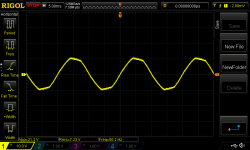
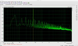
I take the output of the pre-amp and feed it into the sound card. While watching the Spectrum Analyser in ARTA I set the levels on the sound card so that there's no clipping. The attached image is a clip of the ARTA Spectrum Analyser window (32x linear averaging). You can see from the cursor reading that the 400Hz signal is -4dB.
I can then measure the voltage peak-to-peak at the output of the sound card (which should equal the voltage at the input of the measurement pre-amp) with my scope. I can also measure Vpp at the output of the measurement pre-amp. At the output of the sound card I measured 240mVpp. At the output of the pre-amp I measured 2.72Vpp. This is not at all the voltage gain I was expecting from the measurement pre-amp (with schematic shown in post 272).
I probed the output of the first LT1677 op amp (OA1). It measured 480mVpp for a voltage gain of just 2x (versus a modelled 32dB or 38.9x voltage ratio). Clearly there's a problem here. The gain for the second stage feels a bit light as well at 5.7x (vs 6.9x modelled). Maybe we can let that slide.
I checked all the resistor values on the board. They seem fine. If the negative terminal of C8 wasn't properly grounded (I left these pads too small for my liking) there'd be unity gain at the first stage. So it must be the op amp and it's an absolute pain to get to...
Is there an error in my thinking?
Attachments
Maybe it would boost your confidence in this new and unfamiliar measurement apparatus configuration, if you used it to measure three or four circuits that are Known Good and whose output-vs-input behavior is Known. Whatever's easiest for you and the parts in your junkbox and the available space on your least populated solderless breadboard. (You do own several solderless breadboards do you not?)
_
- an eleven-to-one voltage divider (Rtop=10K, Rbot=1K)
- a gain-of-negative-one amplifier (Opamp and two 10K resistors)
- a gain-of-positive-two amplifier (same opamp and same two 10K resistors)
- an RC lowpass filter that drastically attenuates your input frequency and whose expected output amplitude can be calculated using EE math or simulated using LTSPICE
_
Last edited:
I order all my e24 resistors in 100s.Also order 100pcs each of 100R, 470R, 1K, 4.7K, 10K, 47K, 100K, 470K.
Rapid and others charge about £1.50 to £1.80 per 100
I have started building a stock of thin film 805 smd in roughly E6 range but due to much higher cost generally in quantities of 10s or 50s depending on quantity discount.
Sure. (I own only one breadboard. I will think about getting more as well as the resistors. I have tons of Panasonic ERJ-8ENF 1206/3216M resistors; just not so many thru-hole.)
But the examination of the measurement amplifier is a simple voltage in, voltage out analysis. (I just used ARTA to provide a sinus.) I'm simply not getting anywhere near the gain I should be (according to my scope Vpp measurements). Before I pull the op amp it would be good to know I haven't overlooked other obvious potential causes of the problem.
But the examination of the measurement amplifier is a simple voltage in, voltage out analysis. (I just used ARTA to provide a sinus.) I'm simply not getting anywhere near the gain I should be (according to my scope Vpp measurements). Before I pull the op amp it would be good to know I haven't overlooked other obvious potential causes of the problem.
- Status
- This old topic is closed. If you want to reopen this topic, contact a moderator using the "Report Post" button.
- Home
- Amplifiers
- Power Supplies
- Enough current to turn on 3 mosfets?