Thanks again.
Good. It is built onto this board only to measure the three supply voltages that run across it. I won't get out my scalpel just yet.
The gains have been set so that the second stage is just less than 1/5th of the first. So 40.3x for the first stage and 6.9x for the second. Earlier in this thread Mark kindly pointed me to RIAA work by Walt Jung which maintained that the first gain step should have very low noise and high gain. His early version had a first stage gain of 25x while a later version had gain of 50x. In the end I settled on 40x for the first stage. Mark also highlighted work which suggests that the second stage noise is largely irrelevant if the second stage gain is no more than 20% of the first.
I need to refresh my memory as to why I selected 2.49kR for all the resistors except R7 and R10. It was around post 200 or so. (I should have kept better notes...)
Got it - thanks
Err... Not sure. The 14Vp was what ARTA spat out when I did the loopback having entered 1.28Vp (the output voltage).
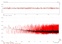
The input sensitivity is set with the dials (one for each channel) on the front of the Quad Capture. The box can also be controlled from the desktop via a control panel software. Images attached. The specs say:
I'm using 1/4in TRS (phono) - RCA adapters. Hmm, if the input is being attenuated then presumably my scale is way off? (even if the pre-amp gain is correct)
BTW what would be the cause of the 50Hz spike in the spectrum analysis? I thought rectification ripple was 2x mains frequency which in my case is 50Hz.
Yes, pretty sure. If the scale is somewhere near accurate, that'd be something like 10uV @ 50Hz, times 300 = 3mV output swing of the preamp.
If that's all you want to measure with it - ripple on the psu - you'll be fine.
Good. It is built onto this board only to measure the three supply voltages that run across it. I won't get out my scalpel just yet.
Try to reduce the feedback resistors of the first amp for lowest possible noise. I went with 1k and 10R, which should be easy to drive by any opamp at such low signal levels.
The gains have been set so that the second stage is just less than 1/5th of the first. So 40.3x for the first stage and 6.9x for the second. Earlier in this thread Mark kindly pointed me to RIAA work by Walt Jung which maintained that the first gain step should have very low noise and high gain. His early version had a first stage gain of 25x while a later version had gain of 50x. In the end I settled on 40x for the first stage. Mark also highlighted work which suggests that the second stage noise is largely irrelevant if the second stage gain is no more than 20% of the first.
You are free to trade gain for bandwidth and vice versa, as long as (1st stage gain x first stage ein) is > 5x (second stage ein). In the case where the first stage and second stage are built with identical opamps, ein1=ein2, making the math even simpler.
I need to refresh my memory as to why I selected 2.49kR for all the resistors except R7 and R10. It was around post 200 or so. (I should have kept better notes...)
Crosstalk from output to input is nasty. Try if it does that with no cables connected, too (which would be really bad); else try other cables.
Touching a coupling capacitor makes you the antenna for every kind of EMI and ugly stuff.
Got it - thanks
Edit: Does your input really handle 14Vp (almost 10Vrms) with sensitivity set to minimum? This looks more like an attenuator than a preamp. You set the input sensitivity via software?
Err...
Not sure. The 14Vp was what ARTA spat out when I did the loopback having entered 1.28Vp (the output voltage).The input sensitivity is set with the dials (one for each channel) on the front of the Quad Capture. The box can also be controlled from the desktop via a control panel software. Images attached. The specs say:
NOMINAL INPUT LEVEL
Input jacks 1, 2 (XLR type) -60 to -6 dBu
Input jacks 1, 2 (1/4-inch TRS phone type) -50 to +4 dBu
I'm using 1/4in TRS (phono) - RCA adapters. Hmm, if the input is being attenuated then presumably my scale is way off? (even if the pre-amp gain is correct)
BTW what would be the cause of the 50Hz spike in the spectrum analysis? I thought rectification ripple was 2x mains frequency which in my case is 50Hz.
Attachments

Last edited:
Hmm, if the input is being attenuated then presumably my scale is way off? (even if the pre-amp gain is correct)
Should be ok at the input sensitivity was calibrated in ARTA against a known output voltage with the input sensitivity set at the level then used for measurement.
Hook up your preamp, fire up ARTA (without averaging and a smaller FFT value for a higher refresh rate), and then watch the spectrum as you move a plugged in mains cord along your preamp. Then try to arrange and route all your cables and stuff on the bench for the lowest possible noise...
BTW what would be the cause of the 50Hz spike in the spectrum analysis?
50Hz, 150Hz, 250Hz, 350Hz etc.
Ok you are suggesting it is likely EMI. I will do as you suggest. (I had actually watched that video quite some time ago.)
The gains have been set so that the second stage is just less than 1/5th of the first. (...)
Keep your gain the same, just reduce the resistor values in proportion, like halve or quarter of what you used. Or start out with 10R for the smaller one and pick the bigger one for your desired gain. Since you're not doing anything RIAA here, it doesn't have to be exactly 299.000587...
Err...
Seems a little high to me. The +4dBu from the spec sheet translate to roughly 3.5Vpp or 1.22Vrms, which is far less than 10Vrms.
Easy sanity check: Set your ARTA gen to -3dB and measure the output with the scope. I assume 1.28Vp is what you will measure. Now connect the loopback and feed the 1.28Vp to the input. 1.28Vp equals 0.905Vrms, which equals roughly -0.9dBV - and that is what you should read in the spectrum with the scale set to dBV. If your reading is way off, then there's something fishy.
Edit: Remember to obey the ext. preamp gain setting! Always enter '1' when doing a loopback without external preamp!
Last edited:
Edit: Remember to obey the ext. preamp gain setting! Always enter '1' when doing a loopback without external preamp!
Yes, I have been caught out before.
Keep your gain the same, just reduce the resistor values in proportion, like halve or quarter of what you used. Or start out with 10R for the smaller one and pick the bigger one for your desired gain. Since you're not doing anything RIAA here, it doesn't have to be exactly 299.000587... :roll eyes:
ok. I need to read AN-581 again. I recall that if you lower the resistance you shift the poles and so it was a bit of a juggling act. Don't worry, I knew it didn't have to target exactly. My modelled gain is 287.8x.
Seems a little high to me. The +4dBu from the spec sheet translate to roughly 3.5Vpp or 1.22Vrms, which is far less than 10Vrms.
Easy sanity check: Set your ARTA gen to -3dB and measure the output with the scope. I assume 1.28Vp is what you will measure. Now connect the loopback and feed the 1.28Vp to the input. 1.28Vp equals 0.905Vrms, which equals roughly -0.9dBV - and that is what you should read in the spectrum with the scale set to dBV. If your reading is way off, then there's something fishy.
The input sensitivity was dialled all the way to the left. I take that to be -50dBu. But see the third pic in post 298. I did exactly as you write and got -0.9dBV.
If I get a Juli@ this will be a non-issue.
EDIT: what settings do you recommend I use in Spectrum Analyser?
Last edited:
I did exactly as you write and got -0.9dBV.
Then your dBV scale should be accurate.
I just noticed that you have set a 32k FFT and Kaiser window. Hanning yields slightly better THD values in my case (YMMV), and a higher FFT resolution certainly increases your results. 64k and 16 linear averages is my sweet spot which doesn't take too long to measure and gives close to optimum results. And I just found out that using 1024Hz instead of 1000Hz shifts the harmonics away from the rubbish present in my computer for even better numbers. Worth a try I'd say.
Last edited:
Then your dBV scale should be accurate.
I just noticed that you have set a 32k FFT and Kaiser window. Hanning yields slightly better THD values in my case (YMMV), and a higher FFT resolution certainly increases your results. 64k and 16 linear averages is my sweet spot which doesn't take too long to measure and gives close to optimum results. And I just found out that using 1024Hz instead of 1000Hz shifts the harmonics away from the rubbish present in my computer for even better numbers. Worth a try I'd say.
It only takes a very short while for me to do 32 sample averages even if the FFT is set to 131072. And raising Fs(Hz) allows the frequency axis to extend beyond 20kHz. Why not use it? I need to do some reading on FFT more generally...
BTW regarding resistors and lowering the noise floor...I guess since this pre-amp can only be used to measure the 3 incoming voltage supplies the pre-amp only needs to have a noise floor below the supplies i.e. pushing for a lower floor is just for glory?
16 averages at 128k take almost a minute. Raising Fs increases the bandwidth, but noise floor, too. Maybe there's something 'wrong' with the mac sound interface. When I use Windows Multimedia Driver WDM I get worse results (and a much worse noise floor) than with using ASIO, since one works with 16Bit only and the other with 24Bit.
Edit: 16Bit WDM (red) vs. 24Bit ASIO (black)
Edit: 16Bit WDM (red) vs. 24Bit ASIO (black)
Attachments
Last edited:
128k?
I see 4096, 8192, 16384, 32768, 65536 and 131072 under FFT. (Under Fs(Hs) I have: 8000, 11025, 16000, 22050, 32000, 44100, 48000, 88200, 96000, 192000.)
At 48kHz, 131072 for FFT I do 32 averages in 1 minute 30 seconds. Raising the frequency to 192kHz it takes 23 seconds but, yes, a slightly higher noise floor.
WDM isn't a direct path to the sound card. ASIO is.
If I get to ignore these 50Hz, 150Hz, 250Hz etc spikes and focus on 100Hz, 200Hz etc then even if my actual pre-amp gain is, say, 10% less than the modelled number I input then I think I can be very happy with the result. Of course, I haven't really loaded up the supply under test during any of this.
I really appreciate all the help.
2 raised to the 10th power is 1024**. Computer people call that "1K"
2 raised to the 15th power is 32768**. That's 1024 times 32 and computer people call it "32K"
2 raised to the 17th power is 131072**. That's 1024 times 128 and computer people call it "128K"
**in decimal notation
2 raised to the 15th power is 32768**. That's 1024 times 32 and computer people call it "32K"
2 raised to the 17th power is 131072**. That's 1024 times 128 and computer people call it "128K"
**in decimal notation
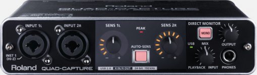
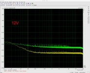
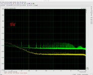
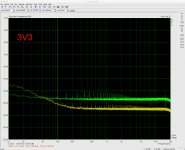
FWIW here are the three voltage supplies using 48kHz, "128k" and Hanning (32 linear average).
One thing in particular is puzzling me: the 50Hz spike appears only on the voltage rail measurements and not when the pre-amp input is grounded. Yet all three voltages are transported to the pre-amp board and 'on' during measurements (just not connected to the pre-amp input) and the pre-amp is powered by and its Vref is provided by the 5V supply rail. If the 50Hz spike is EMI-related then I am surprised it's not also on the noise floor (grounded input to pre-amp). (I'm also a bit surprised that the noise level below 100Hz for a supply rail can be below the pre-amp grounded-input noise floor.)
One thing in particular is puzzling me: the 50Hz spike appears only on the voltage rail measurements and not when the pre-amp input is grounded. Yet all three voltages are transported to the pre-amp board and 'on' during measurements (just not connected to the pre-amp input) and the pre-amp is powered by and its Vref is provided by the 5V supply rail. If the 50Hz spike is EMI-related then I am surprised it's not also on the noise floor (grounded input to pre-amp). (I'm also a bit surprised that the noise level below 100Hz for a supply rail can be below the pre-amp grounded-input noise floor.)
Attachments

One thing in particular is puzzling me: the 50Hz spike appears only on the voltage rail measurements and not when the pre-amp input is grounded.
I suppose that's all right. What does the noise floor look like with the preamp input connected to one rail, but no mains input to the psu? If I'm not mistaken, you'd have to power the preamp with another 5V supply to test this out...
(I'm also a bit surprised that the noise level below 100Hz for a supply rail can be below the pre-amp grounded-input noise floor.)
That's strange indeed. I have no clue.
Ugh...Ignore the plots in post 314; they're complete rubbish. (I forgot to ground the PSON pin of the TPS3510 to allow voltage to flow through the pass transistors.) It's a wonder they're not identical though...
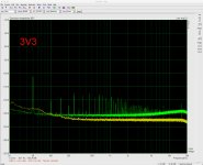
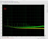
Revised attached. Still with no output load on the supply rails other than the pre-amp/control board (and leakage etc). Interesting that the 5V is the worst and has that larger 50Hz spike. It powers and biases the pre-amp and supplies the TPS3510 circuit.
I ordered a Juli@ xTE card which should have a better baseline THD+N.
Attachments
BTW, push the resistor values down too far and it seems one risks gain peaking. See attached .asc. I will take them down to the values marked in blue on the LTspice file and leave them there. I may as well round the total gain to 50dB while I am at it.
Attachments
BTW, push the resistor values down too far and it seems one risks gain peaking.
Looks minimal in your sim. I put a couple dozen picofarads in parallel with the upper resistor to counter that. Of course you can't go lower than a certain point; 100R and 1R seems to be much too low for the LT1028.
- Status
- This old topic is closed. If you want to reopen this topic, contact a moderator using the "Report Post" button.
- Home
- Amplifiers
- Power Supplies
- Enough current to turn on 3 mosfets?