More importly, how many thinks the BH topopogy is a way forward?
I don't think so.
An externally hosted image should be here but it was not working when we last tested it.
This is just a combination of Ultralinear lNFB, and parallel lNFB (output plate to output grid). The parallel NFB has two voltage dividers in its path: 47K and 0.5x16K as the first divider, and the 200K plate loads || rp || 470K. That pretty much limits its use to drivers with very high rp's otherwise you lose most of the lNFB.
This was done to avoid the Miller Effect magnification of the 47K feedback resistors that would otherwise make for a very tough plate load for the triodes. I prefer using grid drivers (cathode followers/ source followers) to isolate the last voltage amp from the finals.
Ideal always depends on the original goals. An EL84 version of the Vacuumstate PP-1c would certainly be in the running.
Schematics
(scroll down)
dave
Schematics
(scroll down)
dave
I prefer using grid drivers (cathode followers/ source followers) to isolate the last voltage amp from the finals.
The BH described in this thread offers both options.
What I'm running now is the schematic at post #602.
Source Followers with active loads, direct coupled to the output tube grids.
Not sure how many of these have been built - some guys have built more than one.
Would guess there are at least 20 or 30 BH's out there.
Still have a version with pentode diff amp on the front end (2 x 6BR7) on the drawing board. The active loaded source followers will be retained. Thinking of doing a PCB for this and including bias servos for the output tubes.
A couple of Git Amps to finish first but when I retire from the day job and start building tube amps for "pocket money" I will be building BH variant HiFi Amps rather than Git Amps, why? Coz guitar players never have any money.
Cheers,
Ian
The current source biasing in the "simple" BH circuit at post #7? works well but as with many simple ideas it has a "down side". When driven into overload that form of biasing has the worst overload recovery of any of the biasing schemes. The fixed bias variant from post #602 doesn't suffer that overload recovery problem but the fixed bias imposes its own limitations. Namely that the maximum grid leak resistor on the output tubes must be much smaller. That new problem is stepped around by adding the mosfet source follower with the output tube grids direct coupled to the source follower output.
The source follower performance is "spiffed up" by using a current source load rather than a simple resistor load.
Cheers,
Ian
The source follower performance is "spiffed up" by using a current source load rather than a simple resistor load.
Cheers,
Ian
PCL 86 Baby Huey on PCB
Hi tubes lovers,
My first message on the forum, I hope I will not make too much mistakes!
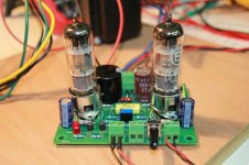
I have read all the discussion on the Baby Huey and I decided to build one, however as a first test (and because I had a bunch of PCL86) I have build the Gingertubes variant of Yves circuit. Since I wanted to make it very compact and easy to build and because no one seems to have done it, I made the choice of drawing a PCB...
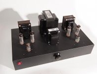
Here you can see the result, and as many have already reported, I was very impressed by the quality of this small amplifier and by the power available with only two small tubes. I have not optimized the adjustment yet but it is working very well. Only one mistake on the PCB i choose a resistor too small on the high voltage filter, I had to change it later by a 4W version...
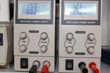
The filaments are powered with a lab power supply at 12.6 V DC and the 4 tubes consumes 1.18 A (they are specified at 300 mA each). For the dephaser, I use an other power supply at - 15 V and for the high voltage I used a Hammond 182L117 toroid transformer behind a non isolated Variac. I made test at 200, 230 and 245 V AC which give me 262, 302 and 324 V DC on plates.
Next project a Bigger PCB for the EL84 version...
Thanks for all the good ideas of smart people available in this forum.
Marc
Hi tubes lovers,
My first message on the forum, I hope I will not make too much mistakes!
I have read all the discussion on the Baby Huey and I decided to build one, however as a first test (and because I had a bunch of PCL86) I have build the Gingertubes variant of Yves circuit. Since I wanted to make it very compact and easy to build and because no one seems to have done it, I made the choice of drawing a PCB...
Here you can see the result, and as many have already reported, I was very impressed by the quality of this small amplifier and by the power available with only two small tubes. I have not optimized the adjustment yet but it is working very well. Only one mistake on the PCB i choose a resistor too small on the high voltage filter, I had to change it later by a 4W version...
The filaments are powered with a lab power supply at 12.6 V DC and the 4 tubes consumes 1.18 A (they are specified at 300 mA each). For the dephaser, I use an other power supply at - 15 V and for the high voltage I used a Hammond 182L117 toroid transformer behind a non isolated Variac. I made test at 200, 230 and 245 V AC which give me 262, 302 and 324 V DC on plates.
Next project a Bigger PCB for the EL84 version...
Thanks for all the good ideas of smart people available in this forum.
Marc
Attachments
Sure, it was !Hi tubes lovers,
. . . Since I wanted to make it very compact and easy to build and because no one seems to have done it,
Yves.
")
Bonjour Yves,
Sorry for the mistake but I didn't know that you made a PCB, in fact I have seen on your site the nice small ECL86 anplifier but it was made with point to point wiring...
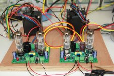
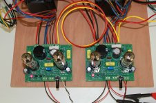
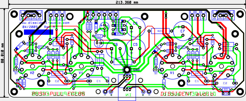
I have seen that you made a star ground on your PCB, I started to design the PCB with the same approach but finaly I wanted to test a ground plane to see if the result will be good and I was not disappointed. I also decided to make mono blocks to be more flexible and to have separate power supply for each channel. I add one photo showing PCL86 heater current, the schematic and the PCB layout.
Now I am planning an EL84 version but I am not sure for which one I should design a PCB the first one or the version with the source followers ?
Any suggestion ?
Sorry for the mistake but I didn't know that you made a PCB, in fact I have seen on your site the nice small ECL86 anplifier but it was made with point to point wiring...
I have seen that you made a star ground on your PCB, I started to design the PCB with the same approach but finaly I wanted to test a ground plane to see if the result will be good and I was not disappointed. I also decided to make mono blocks to be more flexible and to have separate power supply for each channel. I add one photo showing PCL86 heater current, the schematic and the PCB layout.
Now I am planning an EL84 version but I am not sure for which one I should design a PCB the first one or the version with the source followers ?
Any suggestion ?
Is there any sonic advantage to using the fixed bias circuit mentioned in post 602? Probably gonna build a couple monoblocks, and am trying to find the best schematics. Also, any must-have parts or modifications to those schematics?
Fixed bias has a couple of advantages: there is less distortion than with conventional cathode bias, but at the expense of less user friendliness as it will need occasional tweaking and metering. Cathode bias is set it and forget it.
The CCS bias used in the first schemo serves to enforce DC balance in the OPT, but also enforces Class A operation. With fixed bias, there is more output available as the finals can now run into Class AB.
Hi Marc,
No mistake nor offense, your PCB looks cute and clean.
About CCS, I'm not auto bias fanatic -to say no more- but it's effectively user friendly.
And CCS is a "super auto bias"
I did some test on a double PP using 4 x EL84 (a kind of jumboïsed version of the ECL86 original design) and used 4 x CCS to void tedious settings that should be rechecked while tubes naturally wear.
One problem is that each cathode bypass cap charges itself faster than they discharge while playing at loud level and the cathode voltage rises.
(During tests at continuous hi power, they reached more than 25 volts . . . the service voltage of the bypass caps ! !)
I solved that by shunting CCS with a zener diode few volts above the maximum expected cathode voltage for a new and "nervous" tube.
This drastically reduces recovery time after a long "fortissimo" sequence.
Yves.
I finished my Baby Huey amp over the summer and have been enjoying it daily.
I wanted to give a big thanks to Ian and all the other members who helped me through it.
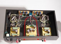
A couple pictures of the final project. It also became a lesson in board etching, as I had never done one before.
-Brad
_DSC0113.jpg
_DSC0115 p.jpg
I wanted to give a big thanks to Ian and all the other members who helped me through it.
A couple pictures of the final project. It also became a lesson in board etching, as I had never done one before.
-Brad
_DSC0113.jpg
_DSC0115 p.jpg
Attachments
Adam1016
The power supply came from a french retailler Selectronic, reference is QJE PS3010, they are very compact and give up to 10 A from 0 to 30 V. You can find it also on several web suppliers like : https://www.aliexpress.com/item/PS3...y-Output-0-30V-0-10A-Support/32350938723.html
To test an amplifier a multimeter will be enough at the beginning, a scope could be used later to control distorsion.
Marc
EL84 Baby Huey on PCB
Hi Yves,
I finalized a first PCB draft based on the first version of the Baby Huey (without the MOSFET follower) I have not yet decided if I will make this version ? On the schematic I have provided the option to use either the feedback from the plates or the screen output of the transformer (even if the last comments from Ian were not very positive for the second solution)... You can find the schematic and the PCB below (for a better viewing I didn't show the top and bottom ground plane which I keep since it work so well).
I am also interested in a quad EL84 version and I agree with you that to adjust 8 trimmers to set a good bias for all output tubes is boring... I was thinking to use some kind of auto-bias like what has been done by Norman Koren in a very nice amplifier, "the TENA" : The Emperor's New Amplifier
This solution will insure that all output tube be perfectly biased all the time !
What do you think about this solution ? This will also simplify the design and reduce the cost since 8 hi-quality bypass cap will be avoided
Marc
Attachments
Hi Marc, this looks very professional, tidy and compact design. If you do make the EL84/ECC83 pcb's I would be very interested to buy a pair (or one if board is for stereo). I was making a point to point version but now would like to build a pcb version. If you do make pcb's could you design it with space for some paper in oil coupling caps. Will you use the Gingertube CCS and Bias block designs? Regards Ian.
- Home
- Amplifiers
- Tubes / Valves
- EL84 Amp - Baby Huey