Marc,
Re-looked at your schematic to see what R17 was doing.
Use both LEDS with no R17 for best results.
These can be both RED or both green or a mix, including blue.
You want the higher operating voltage LED (Red Green Blue is the lowest to highest operating voltage for LEDS) for LED1 for best CCS performance. (That is, use Green or Blue for LED1). The other is not critical, use whatever you like.
I would also change R16 for approximately 2mA LED current. 27K would be OK.
Then set R18 to get the 12AX7 anode voltages in the 160 to 200V range. 157V is OK, a little higher would be better. (This helps keep 12AX7 grid current low).
Increasing R18 lowers the CCS current and raises the 12AX7 anode voltages.
When you have it all running and want to further experiment, try changing R23 from the listed 10 Ohms to 33, 36 or 39 Ohms, all work well. You will then need to re-adjust bias a little for the desired idle current in the EL84s.
Cheers,
Ian
Hi Ian,
Thank you for your very fast answer")
As you have well seen in your second post R17 is only used in the second version with the red LED, in fact I have made the PCB compatible with both solutions to compare them.
As you can also see on the photo with the red LED, R18 is 1.5k like in the previous schematic version, but this gave me about 220V on 12AX7 plates ! That is why I soldered a 2.2k resistor in parallel under the PCB (not visible on the photo) and I got 157V... Now I have removed the 2.2k resistor. I don't know why but I believed that the voltage should have been around 140V, I probably misread one of the post in this long thread ! May be 1.2k could be the good value for R18 ?
Coming back to the first version with the green and the blue LED but without R17 (you can see R17 not mounted on the other photo), even if I changed the resistor R16 or R18 the voltage didn't change enough (only few volt)... May be I have to test other LED's ? I will also change R23 as you suggest, but what is the reason, more local feedback or a better balance between the tubes ?
I will make more measures later, now I am enjoying the Baby Huey singing while I repair and try to improve my old Jolida 502B which made a very bad noise few days ago I found one KT88 in short circuit and the 1 ohm resistor for bias control open !!! Now it is repaired but I replaced the KT88 with SV5550 that I like also, and I will replace the bad quality capacitors inside.
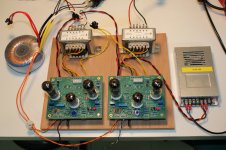
Back to the BH, I forget to say that the output transformer RTU-101 is now giving a good result with the secondary wired on 4 ohms instead of 8 ohms. As you can see on the photo, I have one channel with this transformer and the other one with the Hammond 1609 and I cannot say that one side is better, even with the 80V on the first version. That is an other quality of this amplifier, it give wonderful result even with wide tolerances on the circuit. Congratulation for this smart design, are you planning some new project ? I am looking for a quad EL84 with auto-bias like Norman Koren in his TENA amplifier, I already started a PCB for the power supply with the bias control.
Cheers,
Marc
Thank you for your very fast answer
As you have well seen in your second post R17 is only used in the second version with the red LED, in fact I have made the PCB compatible with both solutions to compare them.
As you can also see on the photo with the red LED, R18 is 1.5k like in the previous schematic version, but this gave me about 220V on 12AX7 plates ! That is why I soldered a 2.2k resistor in parallel under the PCB (not visible on the photo) and I got 157V... Now I have removed the 2.2k resistor. I don't know why but I believed that the voltage should have been around 140V, I probably misread one of the post in this long thread ! May be 1.2k could be the good value for R18 ?
Coming back to the first version with the green and the blue LED but without R17 (you can see R17 not mounted on the other photo), even if I changed the resistor R16 or R18 the voltage didn't change enough (only few volt)... May be I have to test other LED's ? I will also change R23 as you suggest, but what is the reason, more local feedback or a better balance between the tubes ?
I will make more measures later, now I am enjoying the Baby Huey singing while I repair and try to improve my old Jolida 502B which made a very bad noise few days ago
I found one KT88 in short circuit and the 1 ohm resistor for bias control open !!! Now it is repaired but I replaced the KT88 with SV5550 that I like also, and I will replace the bad quality capacitors inside.Back to the BH, I forget to say that the output transformer RTU-101 is now giving a good result with the secondary wired on 4 ohms instead of 8 ohms. As you can see on the photo, I have one channel with this transformer and the other one with the Hammond 1609 and I cannot say that one side is better, even with the 80V on the first version. That is an other quality of this amplifier, it give wonderful result even with wide tolerances on the circuit. Congratulation for this smart design, are you planning some new project ? I am looking for a quad EL84 with auto-bias like Norman Koren in his TENA amplifier, I already started a PCB for the power supply with the bias control.
Cheers,
Marc
On the R23 - See post 451 and 452 for spectrum analyser plots from Sheldon.
In that instance the common resistance was put in series with thw cathode bypass capacitors but same principal applies.
Cheers,
Ian
P.S. In those 2 plots notice that without the resistor there are multiple intermodulation "side bands" around the 1kHz test tone.
These are the 1KHz + and - the residual power supply ripple frequency. Adding the resistor supressed these side bands considerably.
As harmonic distortion and intermodulation distortion are produced by the same mechanism (non-linearity in the push pull outputs) this indicates improved linearity. The audible effect is quite subtle but I think worthwhile.
The resistor is introducing some common mode local feedback. The "magic" value seems to be approx 0.13 to 0.15 of the value of what you would use for separate cathode bias resistors.
That is, 0.13 of 270 Ohms = 35 Ohms for EL84 (33 , 36 or 39 work) or 0.13 x 470 Ohms = 61 Ohms (56 or 62 Ohms work) for 6V6.
Last edited:
Sorry for the lame question, but could you explain "long story short" the advantage(s) of the negative rail for the first stage? I kind of get "the trees" but cant see the forest.
The one big disadvantage of it is that the negative rail has to be well-filtered, I can see the 120 Hz ripples which I do not get with CCS connected to ground.
Sonically I can't hear the difference between it's present vs not. Or, that difference is rather one of "I hear it if I want to hear".
BTW, I am using the CCS on JFET; I remember author's comment on LED+2xTR is more stable - tried both, did not find any audible difference or with measurements.
Also, with both kinds of CCS I observe the slow bias voltage drifting, +/- 10 mV and hectically cycling like 0.1-0.5 Hz - is that common? Tnx.
Shef,
I used the negative rail to make sure I was'nt overdriving the input stage.
The cathodes will sit at half the audio input AC (signal) voltage. With the CCS returned to 0V, and a bias voltage of less than +2V there is a real risk that there will not be enough "compliance" voltage for the CCS to operate.
With a high quality CCS (large impedance) then any noise on the -ve rail will be divided by the ratio of the CCS impedance and the impedance looking into the cathodes of the input stage. This is another "driver" for using the best CCS you can. You should be getting at least 1,000:1 division of -ve rail voltage noise.
I have never observed that bias voltage drift/low frequency oscillation. I assume you are referring to bias of the input stage triodes and not the output tube bias.
Cheers,
Ian
I see.
Yes, my inquire was about the input stage bias, could you elaborate a bit further.
Speaking generally (applied to any diff stage, my amp is not a BH)), without -V rail the bias would be e.g. +3.4V, but with -V applied it could be lowered close to 0, correct?
Hence, otherwise to get the bias that low without -V rail the plate current has to be... cranked up?
Well, let's say the capasitor's been added to the input tube's network, then how the -V rail would improve things? With a cap the bias of + or -3.4V does not make much of difference.
That drift - might be the defective tube, I will check out if I get it with another pair.
I mostly run the amp without global feedback at all - just leave out the 12K.
You can do some quick and dirty math to see what would suit feedback from the 8 Ohm tap.
10 Watts into 4 Ohms => 6.32 V RMS
10 Watts into 8 Ohms => 8.94 V RMS
For same amount of feedback the 12K/470R voltage divider needs adjusting by 8.94/6.32.
That would suggest that the 12K needs to increase to about 17K.
Try 15K or 18K preferred values.
Cheers,
Ian
Hello Ian,
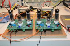
I have finished my Baby Huey and use it every day since one month As you can see on the photo I use a small switching power supply for the heaters.
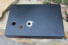
I wanted to built it in a steel Hammond chassis but I break the drill-saw (don't know the exact name in English) and I have to find a better metal worker than me.
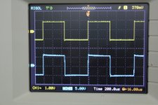
I made some photos of square wave signal but I have no audio analyser and I cannot measure distortion or other data!
Now I will try to make a power supply module based on Norman Koren design to use with a quad EL84 version of the Baby Huey with an auto bias to avoid too much trimming... Here is my preliminary schematic and PCB, but it is not sure that I will build all on one board, may be I will make a board for auto bias only and another for the power supply?
If you have any suggestion, I will appreciate your feedback.
Cheers,
Marc
I have finished my Baby Huey and use it every day since one month
As you can see on the photo I use a small switching power supply for the heaters.I wanted to built it in a steel Hammond chassis but I break the drill-saw (don't know the exact name in English) and I have to find a better metal worker than me.
I made some photos of square wave signal but I have no audio analyser and I cannot measure distortion or other data!
Now I will try to make a power supply module based on Norman Koren design to use with a quad EL84 version of the Baby Huey with an auto bias to avoid too much trimming... Here is my preliminary schematic and PCB, but it is not sure that I will build all on one board, may be I will make a board for auto bias only and another for the power supply?
If you have any suggestion, I will appreciate your feedback.
Cheers,
Marc
Attachments
Looking Good.
I had a quick look at schematics and did'nt see any obvious errors.
For those of you looking at the schematics - The Norman Koren bias servo method is to run one tube, normal, fixed bias as a Master. It's cathode voltage (across the cathode current sense resistor) is filtered by 33K and 10uF which is then used as a reference for 3 slave servos, one for each of the other output tubes.
Cheers,
Ian
Hi there! I'm planning a baby Huey build for my father. Going to build one with and for him. It's been almost 20 years since the last time we did this. A couple of years ago I build my last tube guitar amp. Mind you, the skills are a bit rusty.
I just won a pair of Telefunken power trannies on eBay. Sec. is 260 V 100 mA non centre tapped. Would one transformer be sufficient to drive a mono block. They deliver 3 A heater current, so that should be fine. I remember reading about someone in this thread using a 500 (or so) Vct 150 mA Hammond and finding it to light for a stereo BH. It confuses me a bit. Is 26VA of high tension enough?
I just won a pair of Telefunken power trannies on eBay. Sec. is 260 V 100 mA non centre tapped. Would one transformer be sufficient to drive a mono block. They deliver 3 A heater current, so that should be fine. I remember reading about someone in this thread using a 500 (or so) Vct 150 mA Hammond and finding it to light for a stereo BH. It confuses me a bit. Is 26VA of high tension enough?
I'm trying to understand the feedback in this circuit and wonder if anyone can shed a little light on it. Ignoring global feedback, my understanding is that the cross-coupling resistor creates a 'virtual' AC connection to the plate of the EL84s, mimicking a plate-to-plate feedback scheme (this much is explained in the wiki, I think). I'm trying to calculate how much local feedback this theoretically applies, but I think I might be missing something.
If the feedback factor is Ri / (Rf + Ri). I think we'd use the output impedance of the LTP as Ri here (ball park 50k). Half the value of the coupling resistor in parallel with the 47k is in series with the 220k and would be Rf. I'm calculating the feedback to be around 15-20db with this method, but I think I've seen it quoted as less than 10db in places.
Feedback factor = 50k / (220k + 47k || 8k) ~ .22
Closed loop gain = 35 / (1 + 35*.22) ~ 4.02
20 * log (4.02 / 35) = -19db
Am I off track somewhere?
edit: I'm using the open loop gain for half the 12AX7 differential pair here (35). Maybe that's where I'm going wrong?
Last edited:
Only relevant measurements I did are at post #140
http://www.diyaudio.com/forums/tubes-valves/72536-el84-amp-baby-huey-14.html
May help (or maybe not)
Cheers,
Ian
http://www.diyaudio.com/forums/tubes-valves/72536-el84-amp-baby-huey-14.html
May help (or maybe not)
Cheers,
Ian
Those power trannies will be good, adequate power for a mono block.
Cheers,
Ian
Thanks Ian,
I hope you can help me with the next step. My dad requested a PCB design for this amp, so I made him one. He never worked with PTP and at his age learning that is too much of a challenge. Could you check the design with/for me?
Some resistors are on the tube socket side, mostly the ones that are hard to cool because there are tracks under the resistors. The ground return paths for the CCS's of the power tubes are a bit long, but do not cross low current ones from the ECC83 and its CCS. The CCS of the ECC83 gets its own transformer.
Etching will be done in the kitchen sink, hence everything is single sided. Clearances in B+ are 100mill, around the ECC83 is 50 mil, the rest is 32 mil.
There are some wire pads to get the B+ for the ECC83 from the plates or the screens of the power tubes.


Only did a brief look.
I would add 100 Ohm resistors into tube CCS pass transistor bases (the MJE340) - for stability of the CCS's.
I would also ditch the bias ajustment pots, POT3 POT4, they are not required. You can set the CCS current just by R45 and R57.
Does your PCB layout program have a rules check function.
Define a minimum clearance rule for the likely B+ voltage and check for any violation.
Cheers,
Ian
Only did a brief look.
I would add 100 Ohm resistors into tube CCS pass transistor bases (the MJE340) - for stability of the CCS's.
I would also ditch the bias ajustment pots, POT3 POT4, they are not required. You can set the CCS current just by R45 and R57.
Does your PCB layout program have a rules check function.
Define a minimum clearance rule for the likely B+ voltage and check for any violation.
Cheers,
Ian
Will add the resistors on the bases and get rid of the pots. They were there just for convenience and quick fine tuning of the anode current.
Layouts are done in Cadsoft Eagle, which has a rules check function. You can use different net classes where you can assign minimum track width and clearance per net class. Traces like B+ and anodes of the EL84's are class 1 (high voltage 450V) and have a clearance of 10mil/40V. That should do for uncoated. I get no errors out of the DRC except for the space between the tube socket pins. Best to coat the trace side of the print after soldering me thinks...
Hi,
I'm very interested in the Baby Huey design. But i like octal tubes (6SL7 and 6V6) more than the EL84. I read about an 6V6 design somewhere in the thread so there is no big deal about it.
My problem is that i dont want to wire it point by point. Is there a pcb for an octal version of the Baby Huey?
cheers,
Martin
- Home
- Amplifiers
- Tubes / Valves
- EL84 Amp - Baby Huey