To Zek:
Yep, they are the two protection diodes. If you measure with an Ohm-meter they should be connected in parallel from the + power terminal and to the positive terminals of the decoupling capacitors (one diode for each side).
You may replace these two protection diodes with short circuits and obtain better use of external decoupling, but, evidently you loose the protection. So, if you bypass the two diodes always make sure that your power is connected correctly before turning ON the power supply.
Hi again
A made small mods for my red sanwu 7498e board as learnt in the prevoius pages.
I shorted the diodes in #430 and resolder all points because i see some bad soldering.
I have positive and negative effects:
1 positive is that the noise you can hear from the board above 4kHz -15kHz getting less
2 the ringing at the max power without distortion, see at #422 and #425 is still the same. How can a solve this ringing/distortion topic?
thx
chris
The noise you can hear sounds like it is hiss (white noise).
I can suggest you to try with no signal at the inputs (remove input cables) and connect two 2.2KOhm resistors, one across each input terminal - do you then still hear noise? In both channels?
Hi
Maybe my questions are not clear written. i try again.
")
1
Generally i can hear the freequencies above 4k up to 14kHz from my board if i change the input frequency at my freq-generator (DG1022).
This transmission could come from the big coils ...i guess
this "singals" are now not so loud as the previous test.
2
if a made a measurement with my oszi i can see a distortion/ringing = the sinus gets a strange hiss. (its above 21.8 output voltage -- see at posts # 422 and 425)
this "hiss" gets bigger if i turn louder = so the singal get more distroid..
for my excuse i have to say i did not listend to the board on my LS now...just see this on oszi.
thx
Attachments
Last edited:
So, you mainly measure something you don't like to see. But, what you see may not necessarily be a problem when you use speakers instead (and no oscilloscope).
You evidently measure the output as a differential measurement with both probe-grounds connected to amplifier ground (negative supply) and a probe tip on each output?
You will no doubt see some radiation or residuals from the basic modulation frequency (some 300KHz-500KHz). Avoiding that on your oscilloscope picture will be difficult but it will not be a problem with speakers as you can't hear it and the speakers won't even react to it. Your oscilloscope picture will not be as nice as with a class AB amplifier.
A 400KHz square wave of 24V amplitude, with some ringing due to the chokes, will be seen on an oscilloscope.
I understand that you can hear some high frequency (>4KHz) noise coming from the board itself? That surprises me because the chokes should have a mass that does not allow them to resonate at such a high frequency. Could it come from the fan?
So, you mainly measure something you don't like to see. But, what you see may not necessarily be a problem when you use speakers instead (and no oscilloscope).
You evidently measure the output as a differential measurement with both probe-grounds connected to amplifier ground (negative supply) and a probe tip on each output?
...yes you are very right..this is my measurement method...is that wrong?i am a noob !
You will no doubt see some radiation or residuals from the basic modulation frequency (some 300KHz-500KHz). Avoiding that on your oscilloscope picture will be difficult but it will not be a problem with speakers as you can't hear it and the speakers won't even react to it. Your oscilloscope picture will not be as nice as with a class AB amplifier.
A 400KHz square wave of 24V amplitude, with some ringing due to the chokes, will be seen on an oscilloscope.
if i switch on the freq gen to e.g. 14khz so you can see the 300kHz sinus on the oszi modulated on e.g. 14khz . yes its an class D
I understand that you can hear some high frequency (>4KHz) noise coming from the board itself? That surprises me because the chokes should have a mass that does not allow them to resonate at such a high frequency. Could it come from the fan?
this is not really locatable becaus the fan from my psu (rigol dp832 and the cooling fan for my resistors ar too loud...thanks......... i will check this...
Last edited:
The differential measurement (one amplifier channel at a time) is right. I have heard about people connecting the oscilloscope ground to one output and the probe tip to the other. For bridged amplifiers the last is no good.
In case of trouble-finding with noise issues I like to make it (the grounding) as simple as possible. Your amplifier works at least to some extent.
What about putting it on cheap speakers and use your smartphone (floating due to battery operation) as the music source to get an idea about how it actually sounds? Sometimes the measurement setup disturbs the item under test and you mistakenly believe it is the item under test that causes the misbehavior.
The differential measurement (one amplifier channel at a time) is right. I have heard about people connecting the oscilloscope ground to one output and the probe tip to the other. For bridged amplifiers the last is no good.
i looked at EEVBlog - Dave..how to use an oszi correct
Yes an oszi is not a multimeter !
In case of trouble-finding with noise issues I like to make it (the grounding) as simple as possible. Your amplifier works at least to some extent.
What about putting it on cheap speakers and use your smartphone (floating due to battery operation) as the music source to get an idea about how it actually sounds? Sometimes the measurement setup disturbs the item under test and you mistakenly believe it is the item under test that causes the misbehavior.
Yes...i did this test and is sounds not bad...but at power of approx. 100W 2x50W its not possible with my smal chassis in the "lab" but i will test with my KEF Q100 (actually each 130euro......sorry not diy
)Thanks....
Last edited:
...taks for this evening...
Hi FauxFrench...you are my hero
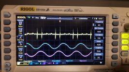
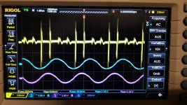
I did some measurments. no inputs singal just power up.
here you can see clearly the 300kHz working PWM of this module.
pics
1st one pic you can see the potentiometer - poti- in nearly mid position.
2nd you can see strange distorion if the poti is nearly at the end!
3rd and 4th i did the 2k2 resistors between the inputs (R to GND, L to GND)....so no changes
Q1
is that normal that i have 2,16Vpp on both channles,...
noise at 4khz and above from coils
yes it comes from the coils!!! both coils from the channel R are noisy!
if i touch it like you press an button the 4kHz noise is nearly gone....the other coils are quite not sensible with this and make no noise.
the probelms with my fan device is underatotal power consumption of 500mA not a Problem @ 30V...but if you push the volume louder you can really hear that 4khz... and the effect if you press this bad coils is very easy to hear!
Q2
What should i try next to stop that noise???
Hi FauxFrench...you are my hero
I did some measurments. no inputs singal just power up.
here you can see clearly the 300kHz working PWM of this module.
pics
1st one pic you can see the potentiometer - poti- in nearly mid position.
2nd you can see strange distorion if the poti is nearly at the end!
3rd and 4th i did the 2k2 resistors between the inputs (R to GND, L to GND)....so no changes
Q1
is that normal that i have 2,16Vpp on both channles,...
noise at 4khz and above from coils
yes it comes from the coils!!! both coils from the channel R are noisy!
if i touch it like you press an button the 4kHz noise is nearly gone....the other coils are quite not sensible with this and make no noise.
the probelms with my fan device is underatotal power consumption of 500mA not a Problem @ 30V...but if you push the volume louder you can really hear that 4khz... and the effect if you press this bad coils is very easy to hear!
Q2
What should i try next to stop that noise???
Attachments
To start with the choke-noise: If you can touch the chokes and the noise disappears, it is very likely that you damp a mechanical resonance in the chokes. The way I know to solve such mechanical resonances is to embed the coils in resin (epoxy). In praxis for you, force a thick epoxy gel in-between the windings and the core with a brush. It will be a bit delicate with the little space on the board. Once the epoxy is cured it should not be possible to generate any sound from mechanical vibration.
You write that you can hear the 4KHz in the speakers if you turn the volume up. That confuses me a bit because then the noise is not only of mechanical origin but is in the electrical system as well. If you push the chokes with your fingers, such that you have no 4KHz choke noise, and then turn up the volume, do you then still have 4KHz in your speakers?
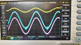
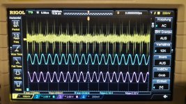
Your scope pictures (very nice oscilloscope):
Blue trace (303KHz / 2,16Vpp), where is that measured? Output signal with a dummy load connected?
Purple trace (303KHz / 2,24Vpp), where is that measured? Output signal other channel with a dummy load connected?
Light-yellow trace (250mVpp-550mVpp), where is that measured?
The blue trace is 90 degrees phase shifted compared to the purple trace.
If the 2.16Vpp relates to the 303KHz residual at an output, after the filter, it is possible. 24Vpp square-wave at 303KHz sent through a second order filter with a cut-off frequency of some 40KHz may leave 2.16Vpp, with some capacitance between the choke windings.
You write that you can hear the 4KHz in the speakers if you turn the volume up. That confuses me a bit because then the noise is not only of mechanical origin but is in the electrical system as well. If you push the chokes with your fingers, such that you have no 4KHz choke noise, and then turn up the volume, do you then still have 4KHz in your speakers?
Your scope pictures (very nice oscilloscope):
Blue trace (303KHz / 2,16Vpp), where is that measured? Output signal with a dummy load connected?
Purple trace (303KHz / 2,24Vpp), where is that measured? Output signal other channel with a dummy load connected?
Light-yellow trace (250mVpp-550mVpp), where is that measured?
The blue trace is 90 degrees phase shifted compared to the purple trace.
If the 2.16Vpp relates to the 303KHz residual at an output, after the filter, it is possible. 24Vpp square-wave at 303KHz sent through a second order filter with a cut-off frequency of some 40KHz may leave 2.16Vpp, with some capacitance between the choke windings.
Last edited:
Thanks a lot ...!
Sorry i do not explain my measuremnt enviroment...
Yes the yellow is the input. i do that on one of the L or R on the 3 pin connector. not on RCA.
the Blue and purple are the outputs on the speakers with 4.6 ohms 40 Watt loads (incl. fan) the connection is gnd to board gnd and the probe of both channels to the + of the speaker output.
noise
sorry i do not write that i hear the noise from coils and speakers. there is no speakers connected. ....the epoxy gel is a very good idea..thanks!
The blue trace is 90 degrees phase shifted compared to the purple trace.
i solder the "hot " line to both "hot" lines of my RCAs. Is that correct? is that the reason why we see hte 90 ° shift????
If the 2.16Vpp relates to the 303KHz residual at an output, after the filter, it is possible. 24Vpp square-wave at 303KHz sent through a second order filter with a cut-off frequency of some 40KHz may leave 2.16Vpp, with some capacitance between the choke windings.
I use 30Vcc PSU. can you explain the las sentensece more.. dos it come from the feedback loop .......i am a noob...
thanks again that you spent your time and knowledge with me
servus
Chris
Maybe you have to connect the probe to speakers terminal + and - (not board gnd), because speakers output has no common ground (as in AB class amps).the Blue and purple are the outputs on the speakers .........
the connection is gnd to board gnd and the probe of both channels to the + of the speaker output......

Maybe you have to connect the probe to speakers terminal + and - (not board gnd), because speakers output has no common ground (as in AB class amps).
no...no..
Watch out...the GND of an osciloscope is earth gnd !!! its not a multimeter!
If you have a battery operated oscilloscope you may connect it straight across the amplifier output terminals because it is tension-wise "floating" (make sure that it is not grounded through a PC you have connected to the oscilloscope).
For an oscilloscope with a net power supply the ground line is "dirty" and may have an unspecified impedance towards the net earth (through the power supply). Therefore, you don't want to load a "clean" amplifier signal line with a line that may introduce important noise and with an unknown impedance.
My view.
Sorry, I am only on the forum occasionally because of family issues I have to take care of. There may be days in-between.
Your yellow scope-trace does not look promising because you have 250-550mV (PP) noise on the line. Without an input signal and a low impedance at the inputs (2.2KOhm) there should theoretically only be a modest noise floor. The spikes we see must either origin from radiation from the rapid output switching, be caused by an inconvenient PCB layout or be generated inside the chip and conducted backward to the input(s). Let's leave that aside for a moment.
For the 90 degrees: It is at the modulation frequency of 303KHz. It hints that the chip designer decided to switch the output switches 90 degrees shifted such that the surge from switching is distributed in time and you achieve double the ripple frequency of the modulation frequency. This is a frequently used trick that lowers the ripple. So, initially no problem.
For the 2.16Vpp/303KHz remains at the output: A class D amplifier works like this that it generates square-wave signal with an average value equal to the instantaneous input signal. The amplitude is almost the supply voltage. The output low-pass filter recovers the average output up to above 20KHz. But, as any other filter, it is not ideal and leaves a small residual (remains) at the output terminals. In your case it seems to be 30V (supply voltage) reduced to 2.16Vpp.The filter is a second order LC-filter with a cut-off frequency of about 40KHz. So, 30Vpp/303KHz on a second order filter with a cut-off frequency of 40KHz sounds like it could result in 2.16Vpp/303KHz. The speakers will never react to such a signal anyway.
Could you please try to connect the amplifier to cheap speakers and try if the 4KHz is heard in the speakers when you turn up the volume control (no input signal / 2.2KOhm to ground) and you press with your fingers on the coils such that they do not emit 4KHz sound?
Servus
FauxFrench
You do not apoligize for your time with your family...please its ok...i am actually on fire to start after work with this diy amp things....so i can wait....sorry to push you.
yes i will do this test with the speakers and the coil test.
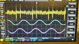
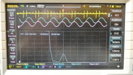
i did another test with FFT measurement, but i am not an expert...
yellow input but without signal no 2k2 resistor...., blue and purple are output channels. with 4.6 ohms load each channel.
30VDC power supply Rigol DP832...maybe the spikea are comming from this device...
you can see the centrum at 302khz, but i can see a peak at neraly 0HZ, whats that ???
once again thanks a lot !!!! merci
You do not apoligize for your time with your family...please its ok...i am actually on fire to start after work with this diy amp things....so i can wait....sorry to push you.
yes i will do this test with the speakers and the coil test.
i did another test with FFT measurement, but i am not an expert...
yellow input but without signal no 2k2 resistor...., blue and purple are output channels. with 4.6 ohms load each channel.
30VDC power supply Rigol DP832...maybe the spikea are comming from this device...
you can see the centrum at 302khz, but i can see a peak at neraly 0HZ, whats that ???
once again thanks a lot !!!! merci
Attachments
Last edited:
Could you please try to connect the amplifier to cheap speakers and try if the 4KHz is heard in the speakers when you turn up the volume control (no input signal / 2.2KOhm to ground) and you press with your fingers on the coils such that they do not emit 4KHz sound?
Servus
Hi
I see this now...The 4kHz are comming from the frequence generator..so it is an input signal.....
I can also switch to the e.g. 11kHz but it is not as loud as the 4 kHz signal. it does not matter. If i do yesterday evening this FFT measurement i try different frequencies but it is the same..the coils ar "sounding/vibrating" and very smal ringing of the fan cooler. to hear this i have to push the amp about 50W in 2x 4,6 Ohms load....more power= more WATT...ringing gets louder
i will try following:
no input signal...smal speakers (visaton FSR8 , 8ohms) and see waht the amp is doing to the speaker....
Status?
Mechanical vibration of coils - can be solved with epoxy gel.
4KHz observations on scope - seem to origin from signal generator.
First audio test only with speakers seemed to be quite successful.
Status?
Mechanical vibration of coils - can be solved with epoxy gel.
4KHz observations on scope - seem to origin from signal generator.
First audio test only with speakers seemed to be quite successful.
Good morning
Before i want to stick the epoxy gel to the coils i realized that during the speakers are playing the coils do not vibrating, so that means the coils are now quiet???? ..if i play over the 4,6 Ohms load you can hear the signals on the coils 4kHz and above.
- Status
- Not open for further replies.
- Home
- Amplifiers
- Class D
- Ebay cheap TDA7498 boards