new measurements with 2x4700µF 35V...
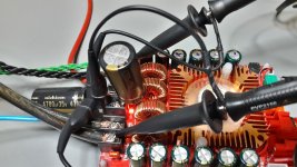
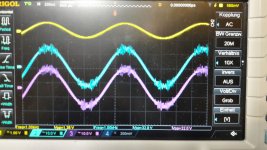
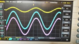
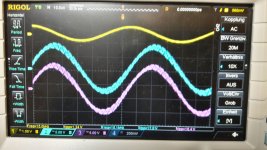
hi again..i did today a short measurement with 2 cpas directly at the board vcc gnd terminal = Nichicon 2x 4700µF 35V
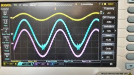
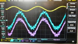
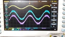
yellow is input
light blue LChannel
pink Rchannel
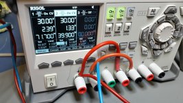
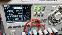
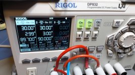
if i made the same measurement setup i got appr. 5 Watt more power.but before clipping its still about 111 watt consumption at 21.8 or 22V max power on the output channel
kr
chris
There is a brief test of this amplifier board on DIYBudgetAudio.com under "TDA7498E based class D power amplifier". No noise observed there and no thermal problems it seems.
Twelve 470uF decoupling capacitors are a good start but not sufficient for such a powerful amplifier if used with a (suitable) power supply to near its full potential. More may be added external of the supply terminals.
hi again..i did today a short measurement with 2 cpas directly at the board vcc gnd terminal = Nichicon 2x 4700µF 35V
yellow is input
light blue LChannel
pink Rchannel
if i made the same measurement setup i got appr. 5 Watt more power.but before clipping its still about 111 watt consumption at 21.8 or 22V max power on the output channel
kr
chris
Attachments
-
 20171230_2x4700uF at VCC.jpg322.2 KB · Views: 555
 -
 20171230_start clipping at Lchannel_2.jpg304 KB · Views: 110
 -
 20171230_start clipping at Lchannel_1.jpg360.8 KB · Views: 100
 -
 20171230_max power.jpg359.1 KB · Views: 106
 -
 20171230_clipping at max power.jpg285.1 KB · Views: 529
 -
 20171230_clean power.jpg352.2 KB · Views: 529
 -
 20171230_before clipping.jpg294.8 KB · Views: 539
 -
 20171230_180w consumption.jpg324.9 KB · Views: 552
Last edited:
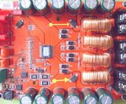
some pics of the too thin thermal fluid on this board. After cleaning its works fine.
That isn't too thin thermal paste, it was just way too much! With the ammount of thermal paste around the chip you can easily do four of them.
That isn't too thin thermal paste, it was just way too much! With the ammount of thermal paste around the chip you can easily do four of them.
thanks ...
...so last thest for today...
i did the same measurements with 3x4700µF 35V caps at the terminals of the board.
now its is easily to move the volume knob to the max power level of my psu.
the 3xcaps are really helpful for my big fat psu !!!
--->
quod erat demonstrandum
--> so always big fat caps for the board --> 3x4700µ = 14100µF
bye
chris
Attachments
Last edited:
Thanks FauxFrench. looks like I don't have to do lot's of modifications. I am going to pair with 30w 8ohm speakers(peak power 50wpc). So I just want 30w clean power. Is 24v 6a psu enough for the purpose? Do you have any cheap but decent psu recommendation? Planning to connect 4700uf (at least 50v) just outside the power supply as you have recommended. But I'm not sure if I can replace those chokes (because it's very difficult to get good quality components here in my country). Thanks again.
For 30W clean power, as you write, 24V is just the right choice. Your initial chokes should just do 30W in 8 Ohm (2A RMS in 8Ohm is 32W) so, as Mark2727 suggested, try with the initial chokes for a start. For moderate power levels and 8 Ohm they will probably do fine and they will be difficult to change because the board is really packed. The problem is if you do 100W in 4 Ohm and require 5A RMS, thus, 7A peak.
How to get a reasonably good power supply for little money: I have a selection of power adapters which I connect to a small board with 10000uF of capacitance and from there, through short leads of AWG16 wire, to the amplifier. A 24V/ 5-6A adapter will cost you some 11-15 Euro and all adapters I have accept the 10000uF at the output. The advantage of such adapters is that they are often designed to look into a load that is not resistive (like a laptop battery) and therefore can handle quite a capacitance at the output.
If you for a start do not have a 24V power supply try to get a 19V adapter (90w) from a laptop (but don't forget the capacitance!). With 19V supply you have 20W output in 8 Ohm.
The power adapters are produced in a really large numbers in Asia and therefore cheap (all mine worked on arrival). The only fact you have to keep in mind is that without the buffer capacitor(s) they may have a dynamically high output impedance and are not suited for a power amplifier that needs a low impedance supply.
I also use Nichicon capacitors or similar because if I can make my amplifiers work well with those (until now I have succeeded) the amplifiers will probably only work even better with Elna or Fraco capacitors. DIY should not be expensive - we need to have room for experiments and sometimes we fail but can afford to fail.
More capacitors in parallel will lower the ESR.
Last edited:
Thank you very much FauxFrench
Thanks FauxFrench for very very helpful post.
I can easily arrange 19v 95w laptop adapter for 5-8 USD which I think will give me 22w at 8ohm. Enough for my purpose. I have some good quality 71v 10000uf Sony blue capacitors. I guess I can make an use of them here. Looks like I have no problem in my hands now. Thanks again.
One last question, if I want to build a 24v 6a psu for this amp, is there any guide/tutorial/schematic any where?
How to get a reasonably good power supply for little money: I have a selection of power adapters which I connect to a small board with 10000uF of capacitance and from there, through short leads of AWG16 wire, to the amplifier. A 24V/ 5-6A adapter will cost you some 11-15 Euro and all adapters I have accept the 10000uF at the output. The advantage of such adapters is that they are often designed to look into a load that is not resistive (like a laptop battery) and therefore can handle quite a capacitance at the output.
If you for a start do not have a 24V power supply try to get a 19V adapter (90w) from a laptop (but don't forget the capacitance!). With 19V supply you have 20W output in 8 Ohm.
Thanks FauxFrench for very very helpful post.
I can easily arrange 19v 95w laptop adapter for 5-8 USD which I think will give me 22w at 8ohm. Enough for my purpose. I have some good quality 71v 10000uf Sony blue capacitors. I guess I can make an use of them here. Looks like I have no problem in my hands now. Thanks again.
One last question, if I want to build a 24v 6a psu for this amp, is there any guide/tutorial/schematic any where?
Did you mean these two diodes?...Lastly, consider short-circuiting the protection diode (polarity protection) found in between the output filter chokes. Then your external decoupling has got more effect.
Attachments
To r_kalar_2:
If you are a real SMPS fanatic you can build your own 24V/6A primary switcher but I wouldn't do it. It is like building your own television just to arrive at more or less the same result as the commercial products, but you pay more to do it yourself and you do not have a suitable box for it, no 230V safety tests etc.
You can look in the data sheets of primary switcher IC's and they will normally show a circuit diagram. But, you have normally very little possibility to personalize your own SMPS (apart from voltage and current) because the IC design sets stringent limits to how it is used in a sensible manner. Also, buying or making the SMPS transformer you need will not be easy.
If I were you I would take advantage of that the Asians produce them in millions and you can buy a safety approved product in a suitable box for very little.
If you can get your hands on a second hand 230V/115V net transformer (with a 20-22V/6A secondary winding) you can design your own linear regulator that will outperform the SMPS (not on efficiency or size) because you have a lot of freedom in the design of linear regulators.
I cannot at present point you to a linear regulator design that is particularly suited for power amplifier use because the dynamic properties are particularly important for amplifier use.
To Zek:
Yep, they are the two protection diodes. If you measure with an Ohm-meter they should be connected in parallel from the + power terminal and to the positive terminals of the decoupling capacitors (one diode for each side).
You may replace these two protection diodes with short circuits and obtain better use of external decoupling, but, evidently you loose the protection. So, if you bypass the two diodes always make sure that your power is connected correctly before turning ON the power supply.
To r_kalar_2:
If you are a real SMPS fanatic you can build your own 24V/6A primary switcher but I wouldn't do it. It is like building your own television just to arrive at more or less the same result as the commercial products, but you pay more to do it yourself and you do not have a suitable box for it, no 230V safety tests etc.
You can look in the data sheets of primary switcher IC's and they will normally show a circuit diagram. But, you have normally very little possibility to personalize your own SMPS (apart from voltage and current) because the IC design sets stringent limits to how it is used in a sensible manner. Also, buying or making the SMPS transformer you need will not be easy.
If I were you I would take advantage of that the Asians produce them in millions and you can buy a safety approved product in a suitable box for very little.
If you can get your hands on a second hand 230V/115V net transformer (with a 20-22V/6A secondary winding) you can design your own linear regulator that will outperform the SMPS (not on efficiency or size) because you have a lot of freedom in the design of linear regulators.
I cannot at present point you to a linear regulator design that is particularly suited for power amplifier use because the dynamic properties are particularly important for amplifier use.
Thanks again. I think that I don't need to build a linear regulated psu for this one. I do have a 230v to +28v-0-28v transformer(which I think isn't suitable for tda7498). But I'll use it for my next project, probably lm3886. Specifically following board:
Shareelec LM3886 Stereo high power amplifier board OP07 DC servo 5534 independent operational amplifier Shen Jin PCB KIT-in Amplifier from Consumer Electronics on Aliexpress.com | Alibaba Group
Any one have any experience with this kind of psu from China? It's inexpensive and perfect for my tda7498 board.
Best quality 24V 5A 120W Switching Power Supply Driver for LED Strip AC 100 240V Input to DC 24V-in Switching Power Supply from Home Improvement on Aliexpress.com | Alibaba Group
Best quality 24V 5A 120W Switching Power Supply Driver for LED Strip AC 100 240V Input to DC 24V-in Switching Power Supply from Home Improvement on Aliexpress.com | Alibaba Group
It looks exactly the same like one of mine. If it is really identical, it should work fine with amplifiers, at least mine did but I used other amplifier modules with it (TDA8932 and TPA3118), not with the TDA7489. According to the datasheet, at 24V the 7498 amplifier delivers 2x60W at 6 Ohm and ~47W at 8 Ohm, at 10% THD, for 1% THD (which is actually realistic for listening quality) you have to subtract ~20-25% (at 36V exactly 22%). That means, you'll have around 2x45W at 6 Ohm and 2x35W at 8 Ohm. The power supply can easily deliver these 90W + the losses, so yes, it will work.
Great. ICG, is your unit from China also? Did you do any modification to it?
Yes and no. Worked fine, no problems. I gave the amp to a friend, he's still happy with it.
Did you mean these two diodes?
Happy new YEAR !
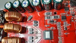
what are the other diodes doing???
all othere diodes (littele smaler -SS14-) are according to the datasheet to protect the outputs L+ /- and Output R +/ - ...... to GND and VCC?
kr
chris
Attachments
Last edited:
- Status
- Not open for further replies.
- Home
- Amplifiers
- Class D
- Ebay cheap TDA7498 boards