^ What do the two switches in the small red housing on the front of the board do?
4 levels of gain can be selected, IIRC
removing volume pots from boards like this is quite difficult.
it is likely you damage some solder holes by pulling the pot out.
i still like that 7498 board and actually build a new boombox around that right now.
i have not decided yet if i just leave as it is and just turn it to max.
the alternative would be to bridge its input and output pins.
it is likely you damage some solder holes by pulling the pot out.
i still like that 7498 board and actually build a new boombox around that right now.
i have not decided yet if i just leave as it is and just turn it to max.
the alternative would be to bridge its input and output pins.
How to get a reasonably good power supply for little money: I have a selection of power adapters which I connect to a small board with 10000uF of capacitance and from there, through short leads of AWG16 wire, to the amplifier. A 24V/ 5-6A adapter will cost you some 11-15 Euro and all adapters I have accept the 10000uF at the output. The advantage of such adapters is that they are often designed to look into a load that is not resistive (like a laptop battery) and therefore can handle quite a capacitance at the output.
I have done exactly same as you have suggested but with two Chinese 2200uf 50v in parallel. Big difference in sound quality according to my ears. Highs are noticeably smoother and bass response became slightly better. I will test it with better bigger caps.
Without any capacitor at the output of the PSU, higher frequency were very sharp. Consequences of cheap SMPS. I have taken advice of TI and put three 10uf ceramic caps at the output. Also added a 2200uf at the input of the amp to act like a reservoir. Result is night and day. I will recommend this kind of cheap mod for every cheap SMPS.
I am very happy to hear about your good results.
When you buy an amplifier based on a single chip, the possibilities to improve the sound may be limited simply because the chip is so dominant for the end result. Luckily, chips we can afford to buy, like the TDA7498 and TPA3116D2, offer so much compared to the price.
But, using a good amplifier with a poor power supply is like driving a nice car on a poor road - it never becomes a real pleasure.
The human ear, I am told, is less sensitive to distortion in the bass range than in the upper mid-range. But, the music transients in the bass range can quickly pull a lot of charge out of the decoupling capacitors such that the supply voltage drops rapidly. Rapid supply voltage drops may influence the mid-range performance.
For what the electrolytic capacitors cost nowadays, need not be the most expensive and they may be recovered from old abandoned amplifiers, make sure that you always have sufficient decoupling of the supply line(s).
Last edited:
Without any capacitor at the output of the PSU, higher frequency were very sharp. Consequences of cheap SMPS. I have taken advice of TI and put three 10uf ceramic caps at the output. Also added a 2200uf at the input of the amp to act like a reservoir. Result is night and day. I will recommend this kind of cheap mod for every cheap SMPS.
10uF Ceramic caps? Do you mean 10pF?
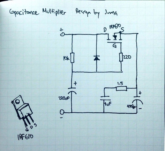
Honestly, I had to look around to find out what is "Juma's Easy Peasy Capacitance Multiplier" (JEPCM). I found it!
It is a nice emitter/source follower circuit used to suppress ripple at a power supply output.
As a purely academic comment, the "multiplier" probably relates to that the circuit used to be implemented with an NPN transistor where the capacitance at the base appears multiplied with the gain of the transistor when seen at the emitter.
With a FET, it is more just a source follower circuit. A nice circuit, but, let us look at how much it solves your problem of buffering the supply line:
At the JEPCM output we have 470uF - not much to supply charge to a hungry amplifier.
Then, we look at the response of the FET. No important charge can come from the capacitor connected to the gate of the FET because it is insulated from the FET-channel and the 10KOhm will allow hardly any current. Thus, the energy has to come from the drain of the FET. The energy supplied to the FET drain has to come from an energy storage upstream of the FET and be supplied to the amplifier through the FET source.
But, if the energy to the amplifier is needed rapidly (this is why we initially use large buffer capacitors on the supply terminals), the energy is rapidly needed at the drain as well. Hence, the energy for the drain again has to come from a storage capacitor. Therefore, a storage capacitor is still needed!
However, there is a difference - the size of the capacitor needed at the FET drain. Before this ripple suppressing circuit was considered included, the ripple at the amplifier supply terminals was directly the ripple at the buffer capacitor(s). With the ripple suppressing circuit inserted, the supply terminals of the amplifier do not see much ripple because the FET source is kept pretty constant by the capacitor at the gate, as long as the voltage (ripple) of the capacitor at the drain does not cause the FET to saturate. If the FET saturates, the ripple filter looses its function.
This means, we can use a smaller energy storage capacitor if we use a ripple filter afterwards because the (increased) ripple of this smaller capacitor is attenuated by the ripple filter.
Just an advantage? Unfortunately not:
Let us use some (rather) realistic values. A FET Vgs of 5 Volt in active mode and a FET saturation (source-drain) voltage of 0.3V. Thus, the ripple at the drain capacitor has to stay within these 5V-0.3V=4.7V worst case. Still much better than without a ripple filter. BUT, the ripple filter has a constant voltage drop of about 5V at any current to the amplifier whereas the initial large decoupling capacitors had no such loss. Though I am very much in favor of ripple-free power supplies, the class D efficiency is set back by losses in the ripple filter. And, the filter capacitor(s) on the drain of the FET needs to stand such high ripple levels.
In conclusion, "Juma's Easy Peasy capacitance multiplier" is a clever idea but not without sacrifices. A trade-off as we engineers often have to balance.
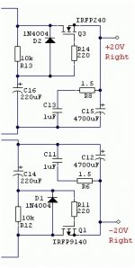
Your part seems to origin from this power supply circuit:
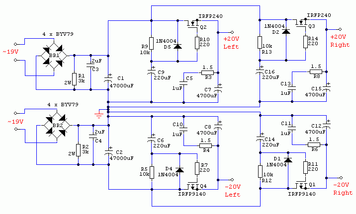
A very serious construction using 2x47000uF before the ripple filters and 4x4700uF after the ripple filters.
I guess the voltage drop will be closer to 4V than to 2V when I study the IRFP240 datasheet.
Such a power supply is applicable when you really want to eliminate the power supply as source of shortcomings in the performance of an amplifier. If we imagine it used, in a single voltage version, for a TDA7498 amplifier I doubt you could hear any difference if you removed the ripple filters and just used the 47000uF and 2uF capacitors. With a good quality 47000uF capacitor(s) and a low ESR 2uF capacitor the ripple on the amplifier supply terminals will be very low even without ripple filters.
Good to see someone so enthusiastic about the power supply design.
Last edited:
removing volume pots from boards like this is quite difficult.
it is likely you damage some solder holes by pulling the pot out.
i still like that 7498 board and actually build a new boombox around that right now.
i have not decided yet if i just leave as it is and just turn it to max.
the alternative would be to bridge its input and output pins.
I removed the pot on my Sanwu board to extend it with wires using a desolder braid. The board handled it fine with no lifted pads.
Your part seems to origin from this power supply circuit:
A very serious construction using 2x47000uF before the ripple filters and 4x4700uF after the ripple filters.
I guess the voltage drop will be closer to 4V than to 2V when I study the IRFP240 datasheet.
Such a power supply is applicable when you really want to eliminate the power supply as source of shortcomings in the performance of an amplifier. If we imagine it used, in a single voltage version, for a TDA7498 amplifier I doubt you could hear any difference if you removed the ripple filters and just used the 47000uF and 2uF capacitors. With a good quality 47000uF capacitor(s) and a low ESR 2uF capacitor the ripple on the amplifier supply terminals will be very low even without ripple filters.
Good to see someone so enthusiastic about the power supply design.
In these past four weeks, I have read all the thread of class d amplifier possible. One thing I have learned and also experienced later that class d amp's sound quite depends on the PSU. But this amps are inexpensive and we are using cheap PSU with them naturally. From tpa3118 thread I have found out that volt+ amp is using a capacitance multiplier for any crappy smps and the result is excellent. If we can build also an easy cheap capacitance multiplier for these cheap tda7498 board and achieve very good result, then it'll be convenient for all who has purchased or is going to purchase. And I believe sanwu tda7498 board I have purchased is better than any Chinese tpa3116/8 board and hassle free. Thanks. You are very helpful.
I removed the pot on my Sanwu board to extend it with wires using a desolder braid. The board handled it fine with no lifted pads.
Thanks for the info.
TDA7498E Red Board
Mine exploded after <1 minute of party power.
4Ohm @ 36V BTLmono melted all 4 of the power pins on the chip.
Looking closely afterwards it really looks like a very poor reproduction, so I'm not surprised.
Question now is where to get an original IC?
Shipping to IRL by recognised suppliers is many times the cost of the chip.
Sorry to hear
Sorry to hear of meltdown! You sure it was due to fake chip?
I just received a 7498 with Bluetooth built on board. As far as I can tell it only has 1 35v 2200 cap on power supply input? Hooked it up tp 19.5vdc 3.5a power brick and it sounded ok. Great treble but vocals a little harsh at moderate levels. Also, it had a pretty loud turn on thump? Board says 24v dc input so maybe why sound a little strained? But won’t more voltage just increase the loudness of power on thump? Wonder how to quiet it down. Any ideas?
- Status
- Not open for further replies.
- Home
- Amplifiers
- Class D
- Ebay cheap TDA7498 boards