Hello mister sanbadgujar
Will this work for you ? I mean I'm not an expert but this might work
Juan
Hello Vargasmongo3435
Thanks for replay. I thinks this pcb is good for me Please give me Bottom toner Transfer layout and detail component top views with size in mm of PCB layout. This is perfect for one channel.
Thanks very much
Attachments
I'm back
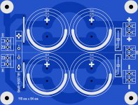
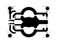
mister sanbadgujar I have problems with my software virtual pdf creator, I can not make accurate size for now here are the files just try to adjust the size to 110 mm x 84 mm
mister sanbadgujar I have problems with my software virtual pdf creator, I can not make accurate size for now here are the files just try to adjust the size to 110 mm x 84 mm
Attachments
Last edited:
I'm back
mister sanbadgujar I have problems with my software virtual pdf creator, I can not make accurate size for now here are the files just try to adjust the size to 110 mm x 84 mm
OK Thanks I got it
Help on Layout
Dear vargasmongo3435
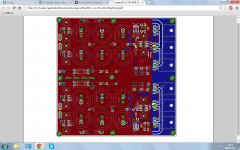
I found PCB Layout in this (dx-blame-st-builders-thread-post-pictures-reviews-comments-here-please)thread. It can be very good for One channel of Dx Blame ST. But in photos bottom layout and top layout its not clear component views can you help on that. I know your busy but I don't have any knowledge of making layout from schematic. can you send me toner transfer layout with detail component views and Size for following PCB layout. please help me
Dear vargasmongo3435
I found PCB Layout in this (dx-blame-st-builders-thread-post-pictures-reviews-comments-here-please)thread. It can be very good for One channel of Dx Blame ST. But in photos bottom layout and top layout its not clear component views can you help on that. I know your busy but I don't have any knowledge of making layout from schematic. can you send me toner transfer layout with detail component views and Size for following PCB layout. please help me
Attachments
Last edited:
Dear vargasmongo3435
I found PCB Layout in this (dx-blame-st-builders-thread-post-pictures-reviews-comments-here-please)thread. It can be very good for One channel of Dx Blame ST. But in photos bottom layout and top layout its not clear component views can you help on that. I know your busy but I don't have any knowledge of making layout from schematic. can you send me toner transfer layout with detail component views and Size for following PCB layout. please help me
Oh .....! I see this is the one you want then ? ok I can figure it out how is all connected just give me a few days I'm kind of busy doing other things but remember mister Nabuco is the original designer we do not usually give away files but only black and white images for etching maybe some one has the black and white images PDF files for etching but sure I can help if there is the case that the PDF images are not available I can "clone " that one no problem my friend
")
Regards
Juan
Last edited:
I apologize in advance because this is a different section dedicated to "Dx Supply, output adjustable, stabilized power supply"
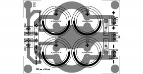
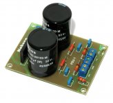
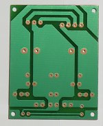
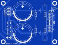
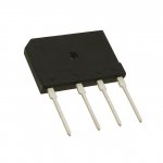
I decide to give some of my time to make this layout, I did a few changes not much, the bridge rectifier is part number GBJ3504-BPMS is a different from the original layout so I adapted to fit the new layout, about the caps you can fit 25 mm , 30 mm and 35 mm diameter caps, I do not have the part number list but so I just place R1,R2,R3,R4,R5 etc, mister sanbadgujar if you have any problem printing let me know I can make a bit smaller or a bit larger if you want,
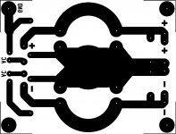
the actual size is 97 mm x 76 mm, the pitch distance of the caps is 10 mm use 2 mm drill bits for them the others 0.80 mm drill bits here are the files. I hope it does work this time for you sir.
Best Regards
Juan
I decide to give some of my time to make this layout, I did a few changes not much, the bridge rectifier is part number GBJ3504-BPMS is a different from the original layout so I adapted to fit the new layout, about the caps you can fit 25 mm , 30 mm and 35 mm diameter caps, I do not have the part number list but so I just place R1,R2,R3,R4,R5 etc, mister sanbadgujar if you have any problem printing let me know I can make a bit smaller or a bit larger if you want,
the actual size is 97 mm x 76 mm, the pitch distance of the caps is 10 mm use 2 mm drill bits for them the others 0.80 mm drill bits here are the files. I hope it does work this time for you sir.
Best Regards
Juan
Attachments
-
power supply.pdf7.3 KB · Views: 218
-
 Power supply simple 5.jpg387.5 KB · Views: 212
 -
power supply layout.pdf16.2 KB · Views: 190
-
power supply layout size.pdf17.1 KB · Views: 199
-
power supply 1 to 1 size.pdf7.3 KB · Views: 202
-
GBJ35005-GBJ3510(GBJ).pdf275.9 KB · Views: 221
-
 GBJ.jpg26.5 KB · Views: 143
Last edited:
Thank you very much
Hello dear vargasmongo3435 sir
Thank you very much for all your help.Now You provide me all I want. It's your very helping behaver All your hard work for me is not common in this world.And don't call me sir please. I am just a student And want to learn some thing in Audio amplifier. Anything I learn in this forum it's a fantastic experience for my life. Thank you all member of this forum who help me enhance my knowledge.Specially Carlos sir vargasmongo3435 sir and Apexaudio,AndrueT. sorry for my bad english
I apologize in advance because this is a different section dedicated to "Dx Supply, output adjustable, stabilized power supply"
I decide to give some of my time to make this layout, I did a few changes not much, the bridge rectifier is part number GBJ3504-BPMS is a different from the original layout so I adapted to fit the new layout, about the caps you can fit 25 mm , 30 mm and 35 mm diameter caps, I do not have the part number list but so I just place R1,R2,R3,R4,R5 etc, mister sanbadgujar if you have any problem printing let me know I can make a bit smaller or a bit larger if you want,
the actual size is 97 mm x 76 mm, the pitch distance of the caps is 10 mm use 2 mm drill bits for them the others 0.80 mm drill bits here are the files. I hope it does work this time for you sir.
Best Regards
Juan
Hello dear vargasmongo3435 sir
Thank you very much for all your help.Now You provide me all I want. It's your very helping behaver All your hard work for me is not common in this world.And don't call me sir please. I am just a student And want to learn some thing in Audio amplifier. Anything I learn in this forum it's a fantastic experience for my life. Thank you all member of this forum who help me enhance my knowledge.Specially Carlos sir vargasmongo3435 sir and Apexaudio,AndrueT. sorry for my bad english
Last edited:
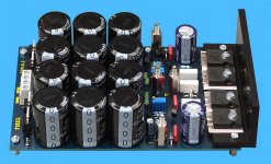
Almost unbelievable they can do this...very cheap..and good capacitors.... high cost these 100V units...high capacitance.
Impressive..no one can compete with these guys...impressive!
regards,
Carlos
I agree, it makes me suspicious about the quality of these capacitors.
Another source for the 6 cap unit.
Wholesale Product Snapshot Product name is Free Shipping 5pcs 6 10000uf amplifier power supply board pcb
Wholesale Product Snapshot Product name is Free Shipping 5pcs 6 10000uf amplifier power supply board pcb
- Status
- This old topic is closed. If you want to reopen this topic, contact a moderator using the "Report Post" button.
- Home
- Amplifiers
- Power Supplies
- Dx Supply, output adjustable, stabilized power supply