And no overshot was found...i would ask another guy that assembled to show his waveforms as i do think this is a special problem happening inside Thimios home, his construction, his pcboard, his parts.
I am sorry, but here are clearly visible basic mistakes in amplifier circuit,the same from early DXamp..It is copy of "basic" schematic for blameless apm, but without any (inevitably for real use) improvement according recovery after fast transients, without any overcurrent protection, with bad compensation and more mistakes.Not your dear friend Juan...he is not your dear friend...his self confidence he have not made any mistake may...not your friend, not helping you or me or the forum...helping his self confidence only.
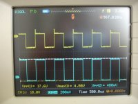
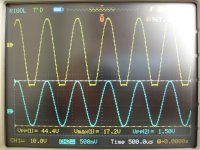
Dear Carlos, try please show (and do not supress questions ) real scope snapshots from output, amplifier driven with load to limitation at 20kHz, for sine and square..It is very mild condition for properly constructed amp.
It is recovery from deep saturation inside amplifier (diferential input and VAS) after positive transient..The same You can see as "sticking" on sine signal (10-20kHz)after clipping.I'm not sure what the little peak is that shows up on the scope
Last edited:
dx super A
I'm surprised with Carlos .
I said again here is a diy forum.
Suppose that i'm stupid but i want build your amplifier.you as the designer must help me not say that i'm not friend. isn't so sik you call other friends not to reply.
Dear Carlos i don't shell nothing no pcb no parts no scopes
In any case suppose i have a mistery fault.
I look for final schematic .....nothing... Carlos don't respond.
i look for other builders scopes.......Carlos show simulation.
I can make another same board with new parts and see what happend but with schematic this time.
"I hooked up my scope and at 50k square wave I see a similar shape as what was shown above"
He isn't my friend.......
Thanks for your help.
Thimios.
Last edited:
I am sorry, but here are clearly visible basic mistakes in amplifier circuit,the same from early DXamp..It is copy of "basic" schematic for blameless apm, but without any (inevitably for real use) improvement according recovery after fast transients, without any overcurrent protection, with bad compensation and more mistakes.
Dear Carlos, try please show (and do not supress questions ) real scope snapshots from output, amplifier driven with load to limitation at 20kHz, for sine and square..It is very mild condition for properly constructed amp.
It is recovery from deep saturation inside amplifier (diferential input and VAS) after positive transient..The same You can see as "sticking" on sine signal (10-20kHz)after clipping.
But what can saturate on 1W 1kHz? In that case something is wrong with parts. Thimios should perform some measurements. If overshot persist in front of inductor that could be the case. If it occurs behind inductor, and with no load, there is parasitic capacitive load on output somewhere.
Uncle Charlie have sensitive reaction when his work come to question so let's be fair. There is nothing offensive here, if we only try to help each other, in view of your design. It is not schematic in question but Thimi's work. Let's help him as is the case on other threads and other designs.
dx super A
I never say that is a bad amplifier.
I never say that is a non functional amplifier.
I never say that i'm sure for all parts and all my job.
40 years in this job i see everything strange.
Those scopes are from mine amplifier not from dx super A.
I wish this is mine problem.
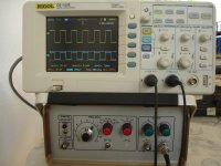
This time i will try to scope in another place with another oscilloscope and another generator .
with and without load again.
Best regards to all ....friends and no friends.")
Thimios.
Thanks overall feedback for reply.But what can saturate on 1W 1kHz? In that case something is wrong with parts. Thimios should perform some measurements. If overshot persist in front of inductor that could be the case. If it occurs behind inductor, and with no load, there is parasitic capacitive load on output somewhere.
Uncle Charlie have sensitive reaction when his work come to question so let's be fair. There is nothing offensive here, if we only try to help each other, in view of your design. It is not schematic in question but Thimi's work. Let's help him as is the case on other threads and other designs.
I never say that is a bad amplifier.
I never say that is a non functional amplifier.
I never say that i'm sure for all parts and all my job.
40 years in this job i see everything strange.
Those scopes are from mine amplifier not from dx super A.
I wish this is mine problem.
This time i will try to scope in another place with another oscilloscope and another generator .
with and without load again.
Best regards to all ....friends and no friends.
Thimios.
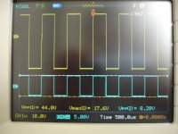
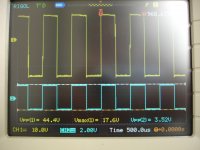
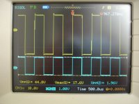
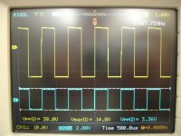
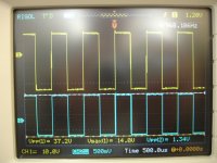
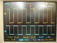
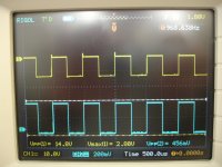
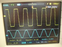
I am not talking about 1W/1khz sine, but about overshot at raising egde of square wave, about visible "steps" at falling edge, about visible unstabilty in negative halfwave, and about lot more ..It is to away from "blameless". Autor should fix it, not to deny any criticism as not friendly.But what can saturate on 1W 1kHz?
I am not talking about 1W/1khz sine, but about overshot at raising egde of square wave, about visible "steps" at falling edge, about visible unstabilty in negative halfwave, and about lot more ..It is to away from "blameless". Autor should fix it, not to deny any criticism as not friendly.
If such nice peak is present on 5Hz square than I expect sine 1kHz sine to reveal weaknesses. But, as I said, thimios should measure it. Uncle Charlie claim that amplifier is not technical but sonic tempered. Maybe there is secret of good sound? Well, maybe we shouldn't discuss it...
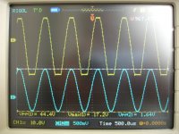
Bad presumtion, this behavior is dU/dT dependant (speed of voltage change)..If such nice peak is present on 5Hz square than I expect sine 1kHz sine to reveal weaknesses
If you call "sonic tempered" instabilty , sticking and overshoots, than yes, is really "tempered". But I call it weakness and mistakes, sorry.that amplifier is not technical but sonic tempered.
Bad presumtion, this behavior is dU/dT dependant (speed of voltage change)..
If you call "sonic tempered" instabilty , sticking and overshoots, than yes, is really "tempered". But I call it weakness and mistakes, sorry.
For dT = constant, it should look different if we change time domain.
edit:
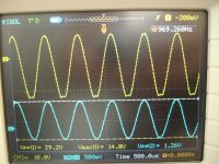
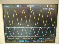
oops, sorry, now I see it is 10 kHz waveform on both pictures, my mistake.
Last edited:
For me it si no surprise.If you don't know already, you will be surprised how many high end topologies are full of weaknesses.
dx super A
I have changed all BC556 transistors with BC560C original philips close matched.
this time offset is 12mV.
I have change out transistors with 2SC 3264 ,2SA1295
I have disable all other modifications .
+-/35v 45000uf / rail
idle current 25mA.
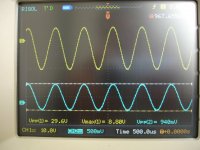
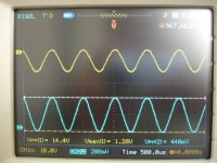
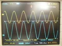
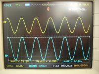
First group photos WITHOUT any load.
Second group photos WITH 8R dummy load.
Please see photos .....AND REMEMBER.THIS IS MINE BOARD NO DX SUPER A
I have changed all BC556 transistors with BC560C original philips close matched.
this time offset is 12mV.
I have change out transistors with 2SC 3264 ,2SA1295
I have disable all other modifications .
+-/35v 45000uf / rail
idle current 25mA.
First group photos WITHOUT any load.
Second group photos WITH 8R dummy load.
Please see photos .....AND REMEMBER.THIS IS MINE BOARD NO DX SUPER A
Attachments
-
 DSC07034.JPG550.9 KB · Views: 484
 -
 DSC07043.JPG533.8 KB · Views: 57
 -
 DSC07042.JPG531.1 KB · Views: 56
 -
 DSC07041.JPG612.2 KB · Views: 54
 -
 DSC07040.JPG572 KB · Views: 54
 -
 DSC07039.JPG601.6 KB · Views: 75
 -
 DSC07038.JPG549.7 KB · Views: 361
 -
 DSC07037.JPG533.9 KB · Views: 378
 -
 DSC07036.JPG543.5 KB · Views: 412
 -
 DSC07035.JPG531.5 KB · Views: 443

dx super A
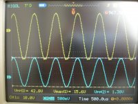
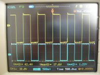
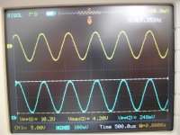
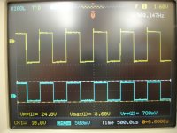
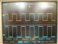
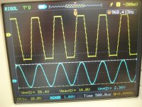
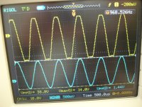
Now the test WITH 8R dummy load.
Now the test WITH 8R dummy load.
Attachments
-
 DSC07055.JPG564.6 KB · Views: 46
 -
 DSC07053.JPG562.9 KB · Views: 46
 -
 DSC07052.JPG542.6 KB · Views: 44
 -
 DSC07051.JPG552 KB · Views: 50
 -
 DSC07050.JPG618.8 KB · Views: 56
 -
 DSC07049.JPG596.1 KB · Views: 54
 -
 DSC07048.JPG586.6 KB · Views: 60
 -
 DSC07047.JPG585.9 KB · Views: 62
 -
 DSC07046.JPG539.3 KB · Views: 69
 -
 DSC07045.JPG600.2 KB · Views: 73
dx
and the rest.
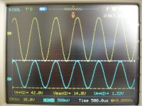
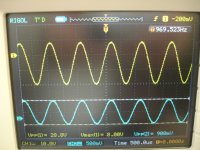
Last photo with 8R dummy and modificated L=4,7uH.
THIS IS A FULL FUNCTIONAL AMPLIFIER WITHOUT ANY ACOUSTIC PROBLEM
TESTED IN ACOUSTIC TEST FOR 3 HOURS CONTINUOUSLY.
and the rest.
Last photo with 8R dummy and modificated L=4,7uH.
THIS IS A FULL FUNCTIONAL AMPLIFIER WITHOUT ANY ACOUSTIC PROBLEM
TESTED IN ACOUSTIC TEST FOR 3 HOURS CONTINUOUSLY.
Attachments
Last edited:
and the rest.
Last photo with 8R dummy and modificated L=4,7uH
Ok, considering bv observations, try to remove capacitor that you decreased from 1u to 100n. It can cause saturation on transients, and uncle Charlie gives the note about it.
This capacitor you mentioned was not degreased by me.Ok, considering bv observations, try to remove capacitor that you decreased from 1u to 100n. It can cause saturation on transients, and uncle Charlie gives the note about it.
This value was printed on Juan pcb.
Do you mean that i should remove it completely?
Many times in my previous messages i have asked for final schematic but..........
Regards .
Thimios.
Last edited:
This capacitor you mentioned was not degreased by me.
This value was printed on Juan pcb.
Do you mean that i should remove it completely?
Many times in my previous messages i have asked for final schematic but..........
Regards .
Thimios.
Yes, just try without it.
About adjustment...some guys are still building
And some of them may need some instructions about how to adjust.
I found this video that was really good, as you see many hits on it...this means it was helpful and may still be good.... was made in 2010
How to adjust an audio amplifier - YouTube
regards,
Carlos
And some of them may need some instructions about how to adjust.
I found this video that was really good, as you see many hits on it...this means it was helpful and may still be good.... was made in 2010
How to adjust an audio amplifier - YouTube
regards,
Carlos
Thank you by your post 1540 dear Terry
Symassim was made with my cooperation...observe the thread and you gonna se the one have opened..and the evaluation of sonics was made together Michael Bitner and another man from Portugal...it is really a nice amplifier.
My amplifiers loose in the bass compared to Symassim and beat in the treble...i know that as i was deeply inserted into the development of this amplifier.
The overshot means the amplifier has some sonic signature that will appear in the high end...maybe something in the pcboard doing that..but this is not bad, as increase treble...when receiving the pcboards i will observe the effect.
I had not the overshot..several videos shows that...this may be parts or construction, pcboard inductance and capacitance creating resonance or tuned circuit.
We had that in the Precision 1...was an increase in 40 Hertz....interesting that happened only dinamically with music playing.... with steady tones, sinus or square..the amplifier was flat, despite in the square we could see the preference to low frequencies by the angle.
I am not surprised with your judgement in comparison....and i agree with you...this is all inside my expectation.
Thank you.
Juan is not here to thank you because the internet in his Island is out from the air.
regards,
Carlos
Last edited:
- Home
- Amplifiers
- Solid State
- Dx Blame ST together Dx Super A