dx super A
I try another function generator.Results are same.
Genarator and amplifier connected via RG58 cable.
I try with 50R and without.Same results.
With same equipments i had test all my diy amplifiers without any problem.
Last one 20W Class A .http://www.diyaudio.com/forums/soli...icon-chip-20w-class-amplifier-opinions-3.html.post#28
Thanks dear AndrewT.
Thimios.
My squarewave source is Hameg function generator HM8030-4 (you can see this in the right side under scope at publised pictures).What is your squarewave source?
What cable connects that source to your test amplifier?
What load is fitted at the test amplifier end of that cable?
I try another function generator.Results are same.
Genarator and amplifier connected via RG58 cable.
I try with 50R and without.Same results.
With same equipments i had test all my diy amplifiers without any problem.
Last one 20W Class A .http://www.diyaudio.com/forums/soli...icon-chip-20w-class-amplifier-opinions-3.html.post#28
Thanks dear AndrewT.
Thimios.
Last edited:
dx super A
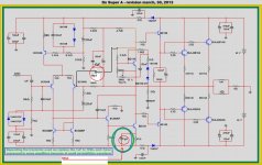
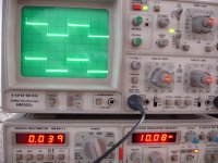
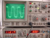
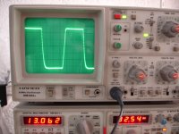
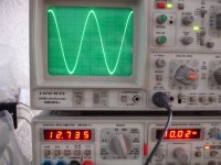
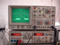
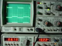
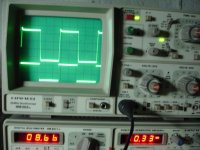
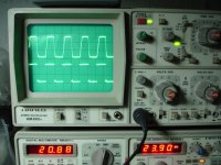
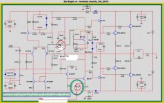
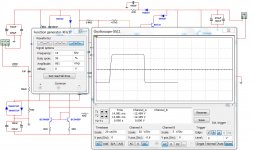
This time i have changed values according to this schematic and i have add a compensation capacitor 10pf as shown from collector of vbe multiplier to base of bc556. Results shown in photos.
First photo .Without compensation.
Second photo.With compensation.
Next 5 photos show some strange things .
I want your opinion about these.
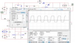
last two photos 32KHz and 60KHz.
Thimios.
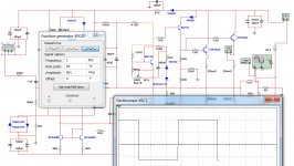
This time i have changed values according to this schematic and i have add a compensation capacitor 10pf as shown from collector of vbe multiplier to base of bc556. Results shown in photos.
First photo .Without compensation.
Second photo.With compensation.
Next 5 photos show some strange things .
I want your opinion about these.
last two photos 32KHz and 60KHz.
Thimios.
Attachments
-
 Super A with updated details.jpg121.2 KB · Views: 421
 -
 DSC07009.JPG542 KB · Views: 382
 -
 DSC07011.JPG534.8 KB · Views: 320
 -
 DSC07012.JPG512.4 KB · Views: 289
 -
 DSC07020.JPG551.5 KB · Views: 73
 -
 DSC07019.JPG522.7 KB · Views: 80
 -
 DSC07017.JPG618.5 KB · Views: 61
 -
 DSC07016.JPG520.8 KB · Views: 63
 -
 DSC07014.JPG515.7 KB · Views: 76
 -
 DSC07013.JPG552.8 KB · Views: 262
Last edited:
Thank you very much dear Thimios so from base of Q2 a 10pF cap to 2k2 input ? can you show and image where is located the connections? I might find and extra space for it, ") "maybe"
"maybe"
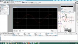
well I'm do not know much about scopes but 32KHz and 60KHz for an audio amplifier is quite a big number maybe AndrewT can explain better, in my mind I will test with 1KHz and 20KHz is the "normal range of testing" but I guess you are a perfectionist guy and that is good, I simulated but with software just for curiosity Carlos did tested many times and all result are good I believe that the test is good in my personal opinion 60KHz is over kill I never try test and amplifier with those frequencies on my simulators but is all cool
best regards
Juan
"maybe" well I'm do not know much about scopes but 32KHz and 60KHz for an audio amplifier is quite a big number maybe AndrewT can explain better, in my mind I will test with 1KHz and 20KHz is the "normal range of testing" but I guess you are a perfectionist guy and that is good
, I simulated but with software just for curiosity Carlos did tested many times and all result are good I believe that the test is good in my personal opinion 60KHz is over kill I never try test and amplifier with those frequencies on my simulators but is all cool best regards
Juan
Attachments
Last edited:
This time i have changed values according to this schematic and i have add a compensation capacitor 10pf as shown from collector of vbe multiplier to base of bc556. Results shown in photos.
First photo .Without compensation.
Second photo.With compensation.
Next 5 photos show some strange things .
I want your opinion about these.
last two photos 32KHz and 60KHz.
Thimios.
Oscillations. Try to increase 150pF on base BC546. (220pF?)
dx super A
Juan this is an image with 39R emmiters resistors.
I told again.Which is the final schematic?
Anyone you know?
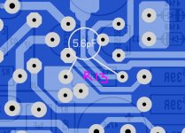
Compansation capacitor better to place underboard ,see photo BUT in my case 10pf is final value.
Oh no just now i see that compansation capacitor is in wrong plase.
I came back later.
Sorry for this .
Thank you very much dear Thimios so from base of Q2 a 10pF cap to 2k2 input ? can you show and image where is located the connections? I might find and extra space for it,
what frequencies you use? I will leave an image here so you can market
best regards
Juan
Juan this is an image with 39R emmiters resistors.
I told again.Which is the final schematic?
Anyone you know?
Compansation capacitor better to place underboard ,see photo BUT in my case 10pf is final value.
Oh no just now i see that compansation capacitor is in wrong plase.
I came back later.
Sorry for this .
Last edited:
Ok dear thanks .Oscillations. Try to increase 150pF on base BC546. (220pF?)
I try it soon.
Best regards to all.
Thimios.
Juan this is an image with 39R emmiters resistors.
I told again.Which is the final schematic?
Anyone you know?
Compansation capacitor better to place underboard ,see photo BUT in my case 10pf is final value.
Oh no just now i see that compansation capacitor is in wrong plase.
I came back later.
Sorry for this .
Is ok don't worried take your time
best regards
Juan
dx super A
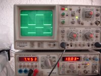
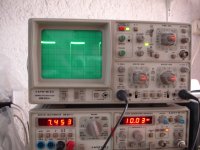
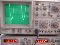
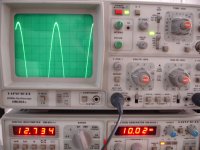
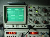
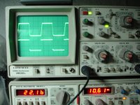
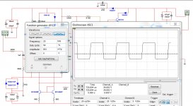
Now i have add a capacitor 5p6 // to 56K feedback resistor.
See photos.
1=Amlifier without any modification
2=5p6//56k feadback resistor.
3,4,5 amplifier WITH TWO(2) MODIFICATIONS. first mod. 5p6//56K, sec. alternative L =5.4uh WITHOUT PARALLEL RESISTOR
Opinions please.
This is not good practice amplifier come unstable.Juan this is an image with 39R emmiters resistors.
I told again.Which is the final schematic?
Anyone you know?
Compansation capacitor better to place underboard ,see photo BUT in my case 10pf is final value.
Oh no just now i see that compansation capacitor is in wrong plase.
I came back later.
Sorry for this .
Now i have add a capacitor 5p6 // to 56K feedback resistor.
See photos.
1=Amlifier without any modification
2=5p6//56k feadback resistor.
3,4,5 amplifier WITH TWO(2) MODIFICATIONS. first mod. 5p6//56K, sec. alternative L =5.4uh WITHOUT PARALLEL RESISTOR
Opinions please.
Attachments
Last edited:
This is not good practice amplifier come unstable.
Now i have add a capacitor 5p6 // to 56K feedback resistor.
See photos.
1=Amlifier without any modification
2=5p6//56k feadback resistor.
3,4,5 amplifier WITH TWO(2) MODIFICATIONS. first mod. 5p6//56K, sec. alternative L =5.4uh WITHOUT PARALLEL RESISTOR
Opinions please.
When you increase inductor, is output loaded?
Yes of course ,dummy load 8R used in all these tests.When you increase inductor, is output loaded?
Regards.
Thimios.
Last edited:
Yes of course ,dummy load 8R used in all these tests.
Regards.
Thimios.
And you said when load is removed there still have to be inductor to suppress peaking isn't it?
I will repeat...these amplifier were tested
And no overshot was found...i would ask another guy that assembled to show his waveforms as i do think this is a special problem happening inside Thimios home, his construction, his pcboard, his parts.
Modifications into the schematic not allowable, not supported and not suggested...amplifier was tested many times, was simulated and no problem happened.
Thimios should search for his mistakes prior to post a bad advertisement that goes against the traditional quality of Dx amplifiers.
Also, nothing about sonics told till this moment...amplifier was made to listen anyway, not to watch waveforms.
I would like ask to friends not to support this discussion, and let thimios exercise the freedom to show his work without the support of you.
This kind of inspection based into a single particular pcboard assembled is not productive..but if more than one find the same problem..then we can believe we have a trouble in the parts or pcboards.
The design passed in many boards assembled..also in scope inspections, you have several videos showing this.... so... at this moment, i believe thimios is a special case and not more than that.
This small capacitor in the NFB line is what unstabilizes amplifiers..maybe his waveforms made with the capacitor instead without it.... the capacitor was supressed several years ago as they do not help any amplifier.
I will not post anymore any comments on that as i do not want to feed thimios show.
If another pcboard present the same problem, then i will give some attention.
Thimios will not be readed anymore..it is not friendly to suppose the amplifier has flaws and to show his own failed amplifier construction as something standard.... not fair the stuff.
If another amplifier present the overshot, then we gonna search in the pcboard the small capacitance in the NFB line that is causing that....not the absence of NFB capacitor, but the inclusion of that by the pcboard lines capacitance or by a component soldered into the pcboard.
Carlos
Last edited:
One more image.
Not your dear friend Juan...he is not your dear friend...his self confidence he have not made any mistake may keep your second batch of pcboards unsold...not your friend, not helping you or me or the forum...helping his self confidence only.
Dudainc is an Acoustic Engineer, famous and working in the whole world, he ordered from you, dear Juan, several pcboard...for sure he would not order to make gift to some friendly customers, something that could have failures.
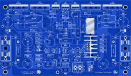
This pcboard, this particular one.... made in China, was not assembled...there is a very small possibility of parasitic capacitances there...i would check as soon this particular one arrive...but i have assembled your layout and anything found Juan...so...relax because you made a great job and soon the guy will come to say the mistake he found in his construction or scope or generator or local interference..for a while..do not feed the stuff.
There will always be people wanting to be noticed.. in Brasil, from time to time someone appear naked when a pop star arrives in hotel..the old search of fame.
regards,
Carlos
Not your dear friend Juan...he is not your dear friend...his self confidence he have not made any mistake may keep your second batch of pcboards unsold...not your friend, not helping you or me or the forum...helping his self confidence only.
Dudainc is an Acoustic Engineer, famous and working in the whole world, he ordered from you, dear Juan, several pcboard...for sure he would not order to make gift to some friendly customers, something that could have failures.
This pcboard, this particular one.... made in China, was not assembled...there is a very small possibility of parasitic capacitances there...i would check as soon this particular one arrive...but i have assembled your layout and anything found Juan...so...relax because you made a great job and soon the guy will come to say the mistake he found in his construction or scope or generator or local interference..for a while..do not feed the stuff.
There will always be people wanting to be noticed.. in Brasil, from time to time someone appear naked when a pop star arrives in hotel..the old search of fame.
regards,
Carlos
Attachments
Last edited:
 order in the room please !
I got home tonight and hooked up my Super A to the scope. I thought I would take some pictures of what I see. I don't usually use square waves. I usually just use a sine wave and look for the point of clipping so I can see how it does. This amp begins to clip at 23VAC into an 8ohm dummy load. I hooked up my scope and at 50k square wave I see a similar shape as what was shown above. At 1K the wave is square. While I was trying to test I lost all output and worried that I had blown something in the amp. After further inspection I saw that the fuses had blown in my cap multiplier. I guess I pulled too many amps while using the square waves. Anyway, I said all that to say this. The amp "sounds" wonderful. I hooked it up today with my speaker switch and had my son, (who is a musician), come in and listen. I compared it to the Honey Badger, Symasym and Leach Superamp. He was unaware of which amp was which when I switched them and he picked the Super A each time. The closest was the Symasym.
Anyway, I'm not sure what the little peak is that shows up on the scope, but it doesn't seem to affect the sound. I did notice that Thimios used the Phillips BC556. I tried those when I first assembled this amp and couldn't get it to work. Once I replaced them with Fairchild BC556 it worked fine. I also installed a STMicroelectronics BD140 at the same time so I can't be sure which did the trick, I just know it worked perfectly after that. I said I wasn't going to do this but I highly recommend these boards. Juan did a great job.
Blessings, Terry
- Home
- Amplifiers
- Solid State
- Dx Blame ST together Dx Super A