DIY amps usually do not carry a VI limiter inside. As DX Blame does not either.ok many thanks...
what do you mean with" excessive input signal"?
is the blame not so reliable????
My son turned the TV off and on, while connected to the amplifier, during a movie. The "thump" generated by the TV audio circuit while turning on was enough to do that. I always connect and disconnect the input cables while the amplifier is off. Or with the volume control set to zero.
I realized this amplifier and it has a great quality of sound and stability.thank you
it seems the same of apex site.
but is it tested and working?
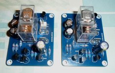
I use this circuit (originally from Silicon Chip Magazine) in my DX Blame ST. One board per channel. It delays speaker turn on, and fast disconnects speakers when main power is off. And the main protection is against DC on the output. Well, I have had one occurence of DC after an exccessive input signal blew up one of the channels (one driver and one output transistor), and nothing happenend to the speakers.
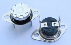
thank you. did you use the thermal switch? it seems to be a thermistor but I never used one before. would you to explain this please?
many thanks
thank you. did you use the thermal switch? it seems to be a thermistor but I never used one before. would you to explain this please?
many thanks
This is a mechanical switch (like on old fridges) that you mount directly on the heatsink. In this case, should be the normally open (NO) contacts type. I would rather install a NC one linked to the input mains, so the transformer would be turned off in case of excessive heat, not only the speakers.
http://www.farnell.com/datasheets/1661840.pdf
No, I did not install this part.
Attachments
Last edited:
Ok!
I think that this part will be not necessary in this amp.
I will use good heatsink and speaker protection. Also an accurate choice of fuses on the amp may be helpful.
My question was about the dc protection, if it was able to work also without the thermistor.
Many thanks
I think that this part will be not necessary in this amp.
I will use good heatsink and speaker protection. Also an accurate choice of fuses on the amp may be helpful.
My question was about the dc protection, if it was able to work also without the thermistor.
Many thanks
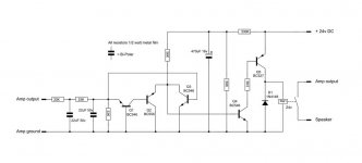
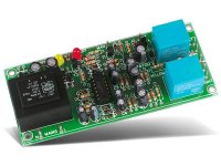
It would be simpler to adopt the following schematic which is identical for DC protection and which has a time delay, to have 24V just add a voltage regulator or a resistive bridge in relation to your supply voltage.
I used this shématic in several amplifiers without problem.
")
I used this shématic in several amplifiers without problem.
Attachments
Ok!
My question was about the dc protection, if it was able to work also without the thermistor.
No need to use the thermal switch. Simply leave its connection open.
hey guys, give me an advice please
considering that I have a single transformer for both channel, could I use a single rectifier for both channel?
in case of no, should I use 2 rectifier bridges wired to the single trafo?
regards
You may use the configuration that better suits your needs:
1) Two transformers and two bridges/array of capacitors;
2) One transoformer and two bridges/capacitors;
3) One transformer and one bridge/pair of capacitors.
It would be simpler to adopt the following schematic which is identical for DC protection and which has a time delay, to have 24V just add a voltage regulator or a resistive bridge in relation to your supply voltage.
I used this shématic in several amplifiers without problem.
It is exactly the same as above, except for this one does not immediately disconnect the output when power is turned off.
Yes, that's what I said.
After disconnecting immediately or not when the power supply is switched off does not matter, what is important is that it cuts off immediately when a dangerous voltage appears on the output of the amplifier.It would be simpler to adopt the following schematic which is identical for DC protection and which has a time delay
I think i will use dx protection as it is a standard type and fully working. Maybe i will use a board with PS and dc protection together.
I have been reading all 184 pages of this tread and I noticed many users had an issue with q6 which has burned several times...because i would build an amp just for listening to some magic, and i wouldn't be worried about any issue...have you definitely solved this problem?
Meanmann told me just to put a 1k resistor between q6 collector and ground but I also read on switching that device with a more robust 2N5551...what do you say, folks?
Regards
Yes, that's what I said.
After disconnecting immediately or not when the power supply is switched off does not matter, what is important is that it cuts off immediately when a dangerous voltage appears on the output of the amplifier.
... if you enjoy the sound of discharging capacitors, it's OK!
The 1K resistor is the correct solution.I think i will use dx protection as it is a standard type and fully working. Maybe i will use a board with PS and dc protection together.
I have been reading all 184 pages of this tread and I noticed many users had an issue with q6 which has burned several times...because i would build an amp just for listening to some magic, and i wouldn't be worried about any issue...have you definitely solved this problem?
Meanmann told me just to put a 1k resistor between q6 collector and ground but I also read on switching that device with a more robust 2N5551...what do you say, folks?
Regards
For the discharge of the capacitors there are 'Bleeder' resistors which are made for this and personally my sound source is always off before the amplifier (I stop the engine of my car with the key and not with a speed engaged... if you enjoy the sound of discharging capacitors, it's OK!
).But basically we agree.
My bleeder resistors are not that fast. So I prefer the output gets cut at once.For the discharge of the capacitors there are 'Bleeder' resistors which are made for this and personally my sound source is always off before the amplifier (I stop the engine of my car with the key and not with a speed engaged
But basically we agree.
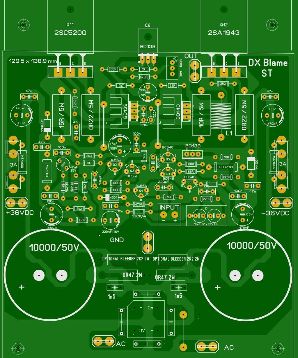
I have looked at the PSU end only.
You are adding capacitors across the rectifier diodes. Why? that increases the risk of ringing.
You have placed two zobels across the main smoothing capacitors. Why.
The correct locations for these Zobels are between the AC input and the transformer Centre Tap. It's the transformer and the rectifier that ring when an impulse appears.
Relabel the GND terminal as CT.
Where is the Speaker Return terminal? I see speaker OUT, but the speaker needs two wires that should be close coupled.
Consider adding an LED to each PSU bleeder to indicate correct voltage (green?).
Consider adding a Zener+LED+resistor to indicate the presence of a high voltage that quickly dissipates as voltage falls.
Last edited:
AndrewT,
Many thanks for your reply.
I will provide to adjust everything you said.
i will use a speaker protection that will have the spkr out terminal so I think to make a link between the spkr out of the amp and the spkr in of the protection.
I would also put together all the returns (from amp/ps, speaker, CT, and also main earth) to a single point on the chassis. It would be good? But in that case spkr positive and spkr return will not run close coupled.
- Status
- This old topic is closed. If you want to reopen this topic, contact a moderator using the "Report Post" button.
- Home
- Amplifiers
- Solid State
- Dx Blame ST - Builder's thread - post pictures, reviews and comments here please.