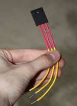
I understand that On Semi transistors are easier to get for guys in Vancouver area. The old favourites like MPSA 56 for BC 556 and MPSA 06 for BC 546 are drop - in replacements here but have reversed pins like 2N 5401/5551.
I hope this is of some help too.
Thanks Finch,
I'll give the MPSA56 a go
I thougth you were almost finishing!...i see you are very carefull and do things slowly not to make mistakes.
regards,
Carlos
Haha, You are correct, I do try to go slowly as not to make mistakes. Mix that will how busy my life is and my low funds. I'm also working on a danzup's source selector extravaganza.
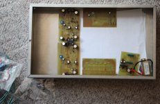
Just a small update, I picked up my enclosure today. It's an 33cm-25cm-7.6cm rectangle, I'm not quite sure what its made out of... sheet metal maybe? I'll post some pictures when I have something mildly completed
Thanks,
Kurtis
Very good Meanman.... have you listened?
Post your evaluation for us as soon as you listen.
It is looking good, despite the big resistances.
The input condenser should not be bigger than 10uf..... increasing it is not increasing bass, the result is reduction of treble.
The amplifier, the Blame ES, is a little bit shy in the low end....the Blame ST, the last version, has much more bass.
regards,
Carlos
Last edited:

 Ahhhhhh! Utube producer Carlos, what has happened to your face.?
This is the terrible face... the warrior face... ready to figth by the soccer
Championship....brazil is ready for the battle in the field of honor, to have the tittle or world champion once again.
Alike New Zeland Native...we paint our faces for war..and we turn ourselves the uggliest possible to produce scare into the enemies.
The battle now is Football!
regards,
Carlos
Championship....brazil is ready for the battle in the field of honor, to have the tittle or world champion once again.
Alike New Zeland Native...we paint our faces for war..and we turn ourselves the uggliest possible to produce scare into the enemies.
The battle now is Football!
regards,
Carlos

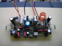
Didn't listen yet but it will be soon.I have to find smaller resistors but when I order 5watt resistors in Europe they're always that big.The white ones from the picture are induction free ones they are wound bifilar I can change them with the MPC71 ones.Maybe there is someone who can make a new layout of the amp for those big resistors?Post your evaluation for us as soon as you listen.
It is looking good, despite the big resistances.
The input condenser should not be bigger than 10uf..... increasing it is not increasing bass, the result is reduction of treble.
The amplifier, the Blame ES, is a little bit shy in the low end....the Blame ST, the last version, has much more bass.
regards,
Carlos
With the correct ones, or with the wrong ones the sound will be great
You should be listening my dear..while you waiting substitution...differences are, but only instruments can capture this..humans cannot perceive such level of details.
All my life i used junk..dirty oxided parts,some having broken leads, flexible wires soldering into the broken leads..well...they do not sound junk when we use junk..... of course..junk does not sound...i could never listen a garbage can producing noises..unless when a cat dive inside catching mice.
regards,
Carlos
Update
I got some more parts! The amp is slowly comin' together. I also know what kind of power-supply I am going to be using; Bora's Universal power-supply without the soft start. The soft start that I am going to be using is Rod Elliott's: Soft-Start Circuit For Power Amps
Some small good news, I'm going to be applying at my local electronics store for summer help, Droping off my application on Tuesday or Wednesday... Wish me luck!
I got some more parts! The amp is slowly comin' together. I also know what kind of power-supply I am going to be using; Bora's Universal power-supply without the soft start. The soft start that I am going to be using is Rod Elliott's: Soft-Start Circuit For Power Amps
An externally hosted image should be here but it was not working when we last tested it.
Some small good news, I'm going to be applying at my local electronics store for summer help, Droping off my application on Tuesday or Wednesday... Wish me luck!
Attachments
I got some more parts! The amp is slowly comin' together. I also know what kind of power-supply I am going to be using; Bora's Universal power-supply without the soft start. The soft start that I am going to be using is Rod Elliott's: Soft-Start Circuit For Power Amps
An externally hosted image should be here but it was not working when we last tested it.
Some small good news, I'm going to be applying at my local electronics store for summer help, Droping off my application on Tuesday or Wednesday... Wish me luck!
Good luck! Also, the amp should be fantastic!
Here is a PCB I made from Rod Elliot's soft start circuit that you mention (should give you ideas how to build)-LINK
EDIT- I don't think you will need a soft start for this project if your transformer is less than 500 VA and you have less than 120,000 uF of capacitence (Carlos calls "condensers"). You will not need nearly that much to realize the full potential of this great amplifier. Maybe 330 VA and 60,000 uF or less. Even my DX has 500 VA and 60,000 uF and blows 5A fuse (I use 6A now, has never blown) but does not need soft start. How do I know? No problems with 6A fuse but ask me again in 10 years and may be a different answer! Of course soft start is fun so use it if you want to experiment or try it out.
Last edited:
I thought that a mild side effect from using a soft start eliminated that pop sound the amp made when you turn it on.
I'm still researching Transformers, the output of this amp is 50watts... and i multiply that by two... 100 watts, and And I'm building two channels so thats at least a 200VA transformer?
If anyone is interested in Boras powersupply, you can find it here. The only alterations that i will be doing will be removing all the 1n4007's (55v rails and soft start circuit) and increasing the capacitance of the 4700uf caps to 6800uf. I will also be reducing the transformer secondary voltage to 24 or 25. Can someone confirm that this will be ok, Bora stopped returning my emails about a month ago, I've heard small rumours about why.
(Bora's website: :::Borina Amaterska Svastara:::)
Thanks for your help!
An externally hosted image should be here but it was not working when we last tested it.
Dx Blame Amplifiers, how to adjust them - vídeos
YouTube - Dx Blame, how to adjust.
YouTube - Blame, starting waveform inspection.
How to adjust to obtain a symetrical clipping, the amplifier fine tuning and how to control overshot will be explained, by email, to the builders only.
regards,
Carlos
YouTube - Dx Blame, how to adjust.
YouTube - Blame, starting waveform inspection.
How to adjust to obtain a symetrical clipping, the amplifier fine tuning and how to control overshot will be explained, by email, to the builders only.
regards,
Carlos
Yes...my voice.... i am preparing another video, will substitute the second one
I have fixed things and will demonstrate... sadly i have perceived oscilations when the amplifier was hard driven with very high frequencies (in the audio band, high frequencies inside the audio spectrum)... when saturated, using square wave i found something strange..... i was using, that time, the Blame ES circuit...that sounds much better, the best one..but is a little bit less stable.
Nothing burned..but i have to say that perfect electronically speaking it is not..but the sound is the best sound i could listen.
How to make symetrical clipping, how to adjust, how to tune... details will be given to builders..to the ones have built..to the ones wants to fine tune it.
Will not post here because theorists will come..and i do not like to discuss theories...first i dislike, second because i am not very good to discuss...so...i feel bad, i can be fooled and became an idiot if the one has bad intentions.
Will not answer theoricall questions, will discuss this only by email, directly with the builders..audio messages and will answer all you want.
carlos.eugenio1951@yahoo.com
But i do not like discuss, also do not like theories...they have not helped me.... in the reality have disturbed me as was used, as tools, by some folks that intended to bother.
I am a practical man....practice is what i know..and only that..i do things listening... i use to calculate..but just to start..then the tuning is by ear....if capacitor there is wrong but sound good..then it will be there correct or wrong.
regards,
Carlos
- Status
- This old topic is closed. If you want to reopen this topic, contact a moderator using the "Report Post" button.
- Home
- Amplifiers
- Solid State
- Dx Blame ST - Builder's thread - post pictures, reviews and comments here please.