OK, thank you. No need for further discussion.
I will find some time to show you the amazing moments we had this weekend provided by a dual Blame ST playing classical music to a group of 19 persons at my home.
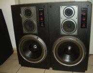
It was a 2 hour show of the Bolshoi ballet, backed by a pair of Sony Sigma loudspeakers.
Good night, got to get some sleep.
Max.
I will find some time to show you the amazing moments we had this weekend provided by a dual Blame ST playing classical music to a group of 19 persons at my home.
It was a 2 hour show of the Bolshoi ballet, backed by a pair of Sony Sigma loudspeakers.
Good night, got to get some sleep.
Max.
Attachments
Last edited:
What happens is that it's not possible to make the correction you mentioned.
And if you had two separete 115V windings, it wouldn't "fit" the two voltages: 127V applied to 115V primary would be saturating the primary (not critical, but not adequate use), and 220V aplied to 230V primary would result in a voltage in the secondaries lower than expected.
Since there's no way to accurately make a two winding primary transformer for both 127V and 220V, the solution is to use a center-tapped one, as used by Toroid on this groupbuy.
Last edited:
Oh!... a small controversy.. automatic invitation to theorists to land here....
A pity these things
and this deviates the thread subject...well... i was thinking , using with my last neuroniuns.... and i found something interesting about....but seems Smartx21 got the point.
Roupa suja se lava em casa (dirty clothing we wash them up in our home)
I remember, of course this happened a long time ago, i used to measure my mains voltage in Rio de Janeiro ....well... a very long time ago folks.... and was 110 volts (not 125V).... and i always imagine i would be loosing something when i faced audio amplifier that had not the real options in their back panel voltage selectors..some arrived with 125-220 switch...... when a back panel knob to adjust more option of voltages would be better...some of them had voltage selectors with 110V - 125V - 220V - 240V indications..and that was better.
I used to appreciate more, the amplifiers, the units that had 110 volts option..and the reason why is because matched the voltage i used to read in my multimeters.
I used to understand (those early days) that if i had an amplifiers adjusted to 125 volts and my mains was 110 volts..that i would be loosing voltage in my secondary as a consequence of my primary transformer voltage selector setting.
So...maybe this is what Smart means.
I also found 127 volts strange... also not clever as a political solution applied from the factory... if calculations where based in 127 when we may have lower voltage in the real world..then secondary voltage may be different compared to our specifications... and this will create some confusion, as our amplifier was rated to 35 volts (100 watts) and will not reach that and this will confuse a lot our beginners (we have some folks that way there)....lower supply voltage may result... and as a consequencey they may not measure the power published..and this matter a lot for beginners..they will feel strange if they find 90 Watts instead of 100 watts.
Is my beloved town, my home town, having 127V in home outlets now a days?....maybe....as i am out since 1989.... and my multimeters...early days.... where analog ones (needle... galvanometer)
Well... the Dx Blame ST can operate from 20 volts (tested) to 42 volts (tested too)... i think it can operate from 12V to 64 without too much modifications and can be adjusted to other voltages too...so....this is not a real problem for us...but..it is really strange this voltage typed in the transformer surrounding white band.... very strange.,,,maybe a typing error only.
Mitchell, as you are one of the best we have in that group..please, ask our boys to measure the real AC output from this transformer.. this gonna be interesting for us... to forecast what we gonna have near future..and we can explain then (you Mitchell!) in advance, what consequences we may have.
I really think someone made the mistake...a trainee or apprentice printed (maybe) a wrong voltage in the surrounding plastic band...the poor guy will be in troubles and very soon... and i feel sad about his destiny, as this created a publish same...now international scandal
This is what i call "electronic bureaucracy".... ou burrocracia.
regards,
Carlos
Last edited:
Sirs, I meant 2x0-115 windings, to be used in series under 220V, and in parallel under 115V, with a correction (not center) tap for 127V. I think that would be more efficient than this old fashioned 0-127-220 way, but I am no engineer at all. Thus I would like to hear from EE which had been the best choice.
Thanks for the inputs, anyway.
Regards,
Max.
Hi smartx21. Quite a disscussion has occured because of this topic. A bit like the ipod/volume control topic
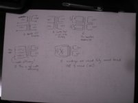
. I think you may be getting confused by the diagrams. Are you thinking that if I connect to 127v tap, then the windings will only physically go half way arround the torroid wasting half the input energy? (diagram D)This is incorrect as if you connect to the center 127v the turns would have physically gone around the torroid at least 1 time or more(diagram e). If you connect to the 220v then the turns of wire would have been around the torroid at least 2 times.Maybe you were thinking something like diagram C. Even if you were to have the primary windings wired in parralel 127v all this means is that the primary windings would be able to handle double the current. This means nothing if the secondary windings are still in series as the secondary current will still be the same. Doubling up of the windings is only used if one wants to double the current ability. I don't think it would make much of a difference to the efficiency.
If you were using 115v windings on 127v supply then your output voltage will be slightly higher. If you use those 2x115v or 230v in series on your Brazil 220v then you will see less voltage on the output then is rated on the transformer. As far as I can see you have custom made transformers for your weird 127v-220v Brazil electricity supply. These are made for your specific country and purpose so you couldn't ask for a better transformer.
The main thing to be looking at is the VA (power) rating of your transformers and not transformer efficiency. If the VA rating is up for the job then you have no problems.
Regards
niss_man
Attachments
Thanks metal, Mitchel, Carlos, Andrew and niss_man. Andrew told what I was thinking would happen: only 58% of the copper been used when under "weird" 127V (you know, they can get exact 220V out of two phases, no neutral, that is the reason for 127V).
Niss_man explained that there is no efficiency problem. So, it is only a waste of copper, waste of money. Hence, no problem at all.
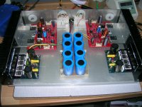
As Carlos says, let´s go on and build the amps. Cases have arrived from Naoko, transformers from Toroid do Brasil, 5600x63 electrolytics from the USA, parts from Hayamax. Only one piece is missing. And we will keep waiting till the end!
Photos to come.
All the best for you all.
Max.
Niss_man explained that there is no efficiency problem. So, it is only a waste of copper, waste of money. Hence, no problem at all.
As Carlos says, let´s go on and build the amps. Cases have arrived from Naoko, transformers from Toroid do Brasil, 5600x63 electrolytics from the USA, parts from Hayamax. Only one piece is missing. And we will keep waiting till the end!
Photos to come.
All the best for you all.
Max.
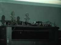
DX Blame show last saturday!
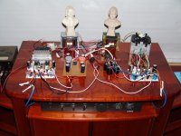
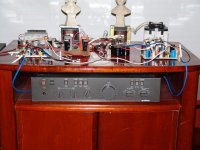
DX Blame ST has done a great job, playing 2 hours of good classical music, with crisp sound, outstanding performance, even with not proper PSU.
Some pictures attached (it was my birthday, there were 19 persons inside the living room!). Last photo: me and friends. Youtube videos being uploaded right now.
This week it will meet the case.
All the best,
Max.
Attachments


First video here:
http://www.youtube.com/watch?v=NDvr7szE75c
And second here:
http://www.youtube.com/watch?v=IEkuOvEaRRg
Don´t get upset: infrared nightshot.
http://www.youtube.com/watch?v=NDvr7szE75c
And second here:
http://www.youtube.com/watch?v=IEkuOvEaRRg
Don´t get upset: infrared nightshot.
Last edited:
The PSU-filter should consist of 0R47 / 1n5 in accordance with Carlos' DX PSU.
Best regards - Rudi_Ratlos
your right, thanks for pointing it... it was copy n' paste i forgot to change the values... and as you said the star connection was omitted
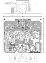
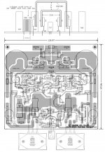
is it nescessary to use fast diodes?here is a revised pcb...
Attachments
- Status
- This old topic is closed. If you want to reopen this topic, contact a moderator using the "Report Post" button.
- Home
- Amplifiers
- Solid State
- Dx Blame ST - Builder's thread - post pictures, reviews and comments here please.