Well Samuel, it is unkind to say that directly this way
You engage your brain and realise your own conclusions without make me figth with so dear friends.
I told have beated all i have built...ALL means something.
I perceive evil in this question Samuel, pray to your God to forgive your behavior (the real God will listen you despite the name you call him), you already know and want to me to say the words.
Bad boy, no icre cream today, no television tonigth!... daddy not happy with you for a couple of hours.
Topologie sounds, so, others having CCS, the same current to differential, the same parts in the input, the current sink, the two stage VAS, the emitter follower output, these currents...then will sound so good as this one..of course!
This way, others may sound almost the same, you have some amplifiers that can do a great job i think, maybe MJL21193, bigun and others have made something alike.
But understand in a more flexible way, advertising is more absolute, but use your mind and reduce the exageration i use to make during advertising (have you ever seen advertising saying the amplifier is regular, very weak but you may tollerate sonics?) , i would like to see friends happy building, so, i use to exagerate a little, the Dx Amplifier, the standard, has more bass,better bass to my TASTE, it is not controlled, not precise,but it is what i like the most..if you analise,or compare, only bass, then the Dx amplifier can beat (the bass only) the Dx Blame ES.
It is Doctor Self input, the Blameless input, the VAS is modified as you see, i am not using CCS to the VAS, also the ouptut is Aksa 55 style...join those characteristics, and of course the sound will be unbeatable too.....But...there is always some small things that helps a lot, i do not know exactly to tell you the capacitor, the combination that produced the result, really, there are things i do not understand and i accept as some "magical combination", a matter of luck, the creator/copier/adaptor man/designer have made the best decisions..this time the lucky one is me.
This amplifier beated ALL amplifiers i have built, from the forum and from outside the forum, since 1969, beated all 5K (around) amplifiers built, beated all i have listened, all Macintosh i have listened, including the tube ones!... the advantage of quality is so great, so clear, so enormous, that you really do not need, even to compare, you can do it to confirmation purposes only, but the difference is the taste of brazilian watter (filled with Chloride, cloro) and a nice mineral watter...the difference between coffee and Chocolate (the last is much better) the difference of the Tea compared to ice cold Coca Cola, the difference you have when you have love with the woman you find and the woman you love deeply.... clear differences.
Other question that way, no more conversations with you dear Samuel...once may be accident, two cannot be.
regards,
Carlos
Last edited:
We do not know what Hugh is doing now, we do not know the schematic and topologie
he is using now a days...i do not know, as the last one i have watched was Maia...it is very possible he may be using something alike, because this is what produces the best sonics and he is "tuned" and deeply skilled...i do not know even how is Maia, the schematic was deleted because of safety and the amplifier is not in my home anymore, it is in my daugther home, other state, 2.5 thousand kilometers south.
I had to start following the Blameless published schematic, the book is there, everybody can see, and they i have removed parts searching for sound, tweaking here and there, including parts, testing, changing currents, trying other ideas, removing CCS, installing Bootstrapp in the place, removing CCS to the differential and installing zener regulator, i have changed all stages currents up and down to see what happens, the driver floating emitter resistance was tweaked up and down, was tested from 15 ohms to 330 ohms!, the suckout was tested using several values, stop resistances included, removed, increase and decreased and several other things done.
I really think Hugh is so skilled that he can go directly using the correct values and the correct topologie without needing so hard work..we do not know what Hugh is doing now a days, but he use to make the best ones, this is the best one, so, i think he may be using something alike this one.
He has some sub circuits, and these ones i have not tried into the Dx Blame ES, but i think his ideas applied may produce another sonics, sadly will have more treble (i think what i have is more than enough, almost excessive) and less bass (and i love bass)
I cannot say can beat Hugh last model, i have not the last model.... but, the emitter follower you see in the Aksa published (this forum) schematic, is Doctor Self output style... seems he has "captured" in the air what is good.
One thing i am sure, Hugh is very, very, very good, much better than me, if i can do that, for sure he could do even a little bit better (there's no room to go up 100 percent quality, now the competition is around tenths)... say... 96, 97, 98, 99, 100... or hundreds, 9.61, 9.62 and so on.
regards,
Carlos
Last edited:
There is something very sad about people, we, humans, we watch without see
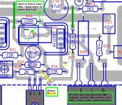
Watch for the very first time dear friends, if you have not really made that before, see this schematic.
Perceive, my schematic is almost Blameless, with some personnal touch here and there...nothing from outside planet, i was lucky to select a good starting point to research only, when others goes loosing time with double differential inputs and other lemons alike.... good friends will accept this as result of my hard work, a good work i have made, i am sure about that...the non good friends, may say was a make up!
ahahahahaha!
regards,
Carlos
Attachments
Last edited:
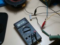
You see boys, the difference we have from the theories and calculations and the real.
world testing.
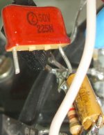
Andrew T suggested 6.8uf for deep bass, Eva said better not to have the suckout, said it is another unstabilizing factor, that i would be searching for trouble, not only, but another one reason of unstabilities.
In a matter of fact, the real thing, sounds not so good without, the good value is 220n, maximum 270n....i have tried this one in parallel, so, my final result would be 2.47uF... but a HUGE power on thump noise resulted, then i cut it out and wait the supply to discharge, and tried once again and no noise....well, i tried several times, i have never imagined the one could do that.
This is the main difference we have, the reseach, the do it by yourself and when we read books, a jesuit thing that really keep us distant from the real world.
They are competent, high skilled folks, very respected in our forum, Eva and Andrew t are one from the very best ones we have to calculate and use theories, Eva seems does thing in real world too.
The suck out capacitor produces power on thump... for me this is a new thing.
Tested, checked and verified several times.... was the capacitor that produced!
this also shows you, and explain you why i use to produce crazy dirty boards, you see, we have to cut parts, introduce parts, remove burned parts, change topologie, and we feel pity to do that with already made beautifull boards, so, this kind of research work, the tweeking work, needs dirty simple fast boards.
regards,
Carlos
world testing.
Andrew T suggested 6.8uf for deep bass, Eva said better not to have the suckout, said it is another unstabilizing factor, that i would be searching for trouble, not only, but another one reason of unstabilities.
In a matter of fact, the real thing, sounds not so good without, the good value is 220n, maximum 270n....i have tried this one in parallel, so, my final result would be 2.47uF... but a HUGE power on thump noise resulted, then i cut it out and wait the supply to discharge, and tried once again and no noise....well, i tried several times, i have never imagined the one could do that.
This is the main difference we have, the reseach, the do it by yourself and when we read books, a jesuit thing that really keep us distant from the real world.
They are competent, high skilled folks, very respected in our forum, Eva and Andrew t are one from the very best ones we have to calculate and use theories, Eva seems does thing in real world too.
The suck out capacitor produces power on thump... for me this is a new thing.
Tested, checked and verified several times.... was the capacitor that produced!
this also shows you, and explain you why i use to produce crazy dirty boards, you see, we have to cut parts, introduce parts, remove burned parts, change topologie, and we feel pity to do that with already made beautifull boards, so, this kind of research work, the tweeking work, needs dirty simple fast boards.
regards,
Carlos
Attachments
Last edited:
2u2F polyester is available as 5mm pin pitch, 7mm long by ~4.5mm wide and ~8mm tall. And it's cheap.
But a 5u6F or 6u8F would be better for deep bass.
I am referring to the input capacitor.10uF and 12k at the input forces all the other electrolytics to be much larger than you presently have them.
At the moment the input filter does not determine the passband of the amplifier.
I believe this needs to be fine tuned to achieve that passive filtered passband.
12k to match the feedback resistor and 10uF gives 120ms filter.
That is greater than 220uF + 470R / sqrt(2) >73ms.
A 5u6F or 6u8F and 12k at the input gives a better match for the NFB loop, but the RC constants around the whole amp need to be re-thought to make them compatible with each other and may bring back the missing bass that you desire.
Yes, no doubts you are rigth, thank you, we have other reasons for the power on thump
one was the increased value on the suckout position.
But for sure time constants in the differential will produce this too, i have finished with this.
I am testing this way, see if i am making any mistake.
I let the input signal entering and them i remove the AC plug, so, i go waiting the 20 seconds needed to discharge my 20 thousand plus 20 thousand electrolitics (time is this one with 1 watt peak).
Then i decrease the input volume, not to have audio entering the power amplifier, the power amplifier input is grounded this way, then i flip the power switch on once again...no more power on thump noise this way.
Next amplifier, to be released March, 28 will have other input impedance, other capacitors, other time constant and other schematic if i suceed to have the stronger bass i love..as i told, the amplifier is electrically flat, but when playing with speaker (not loads, no simulators) things changes a lot, the bass is good, present, but shy compared with the treble and mids... will be release IF the bass was increased without losses in the high frequencies...hehehehe, this is hard to make, will try!
Will try alike an update, this way people will not lost their boards
regards,
Carlos
Last edited:
Perceive, my schematic is almost Blameless, with some personnal touch here and there...
Shameless.

..Todd
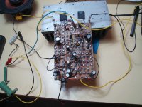
One more brazilian have assembled, this time was Beto, he is from our forum
his name is Egberto (Egbert).
Now we have 5 units built and working fine, his one worked since the first moment, was plug and play, he made point to point construction.
He said, also, this one beated the other ones i have created by ratio of 10 to 1.
regards,
Carlos
his name is Egberto (Egbert).
Now we have 5 units built and working fine, his one worked since the first moment, was plug and play, he made point to point construction.
He said, also, this one beated the other ones i have created by ratio of 10 to 1.
regards,
Carlos
Attachments
his name is Egberto (Egbert).
Now we have 5 units built and working fine, his one worked since the first moment, was plug and play, he made point to point construction.
He said, also, this one beated the other ones i have created by ratio of 10 to 1.
regards,
Carlos
in this one, soldering poins are very distant...this reduce parasistic influence
in the board...
also, you are using power devices that are almost ten fold faster than
the ones douglas self use in his schematic..this could explain
there was more room for oscillations in your version despite the
heavy compensations...
as the diffrence in basses with your others amp, it s difficult to
found a clever explanation, as this one should have very good basses
as the open loop gain is vastly higher at low frequencies..
Yeah, this board style is mine, Beto is a 20 years old friend, we were
Radio Amateurs and we use to be in close contact for years long.
This board i made in 1994, and them i gave it to him.....i am glad he still use this for fast evaluation prototype units.
regards,
Carlos
Radio Amateurs and we use to be in close contact for years long.
This board i made in 1994, and them i gave it to him.....i am glad he still use this for fast evaluation prototype units.
regards,
Carlos
I would ask your attention once again, please
Observe the amplifier was built five times, and two times with the official Taj lovely boards.
Beto did a point by point, almost the same i have done, p2p is very unstable, you have lots of inductances, you have paralell wires in the place to cross them using jumpers avoiding this way capacitances....EVEN this way it is working stable.
So, was proved!, the amplifier is now stable.
regards,
Carlos
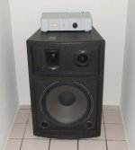
Yes, we have bass!
Not the enormous exagerated double deep and tripple powered bass i love, but we have a good bass...listen!:
YouTube - Dx Blame ES at the torture room
http://www.youtube.com/watch?v=sgtD1-4eLh0
http://www.youtube.com/watch?v=Nja16CTW860
http://www.youtube.com/watch?v=QAKiqTLNd7M
Of course small PC monitoring things, or small speakers, underpowered units having a very small small audio bandwidth cannot reproduce the bass, use the best you have at home, maybe a good headphone.
regards,
Carlos
Last edited:
To the ones does not know, this is the youtube map that shows Europe and the number
of hits, or visitors that have watched the video, the more dark green the more is the number of people visiting.
Thank you all from Europe, i wish i could know the name of each one of you to say thanks,
Most of those ones are not from the forum, but the majority is, because the hits increases when i post the link in this forum.
regards,
Carlos
Attachments

Fifth Dx Blame ES amplifier built in Brasil
http://www.youtube.com/v/K9Ul-DuP3w0&hl=pt_BR&fs=1&rel=0&color1=0x5d1719&color2=0xcd311b&border=1
http://www.youtube.com/v/K9Ul-DuP3w0&hl=pt_BR&fs=1&rel=0&color1=0x5d1719&color2=0xcd311b&border=1
Hold on please!, i have found a small mistake, wait the pcboard versio 1.4
to etch boards,
It is a minor mistake that would not impair the amplifier operation, but it is good to fix that will result in better operation, the driver stop resistance was out from the job he must make.
Soon we gonna have the new pcb version, also the new black lines for etching.
regards,
Carlos
Attachments
Have you ever thought that, at power up, the 2.2uF capacitor has to be charged by the driver transistors and there is nothing limiting the current? Except base current coming from the VAS, which is limited only in one direction.
A big enough capacitor could result in blown drivers at power up, not just a thump.
I can do elementary circuit simulation from memory without many mistakes, and you should be able too...
A big enough capacitor could result in blown drivers at power up, not just a thump.
I can do elementary circuit simulation from memory without many mistakes, and you should be able too...
The amplifier is ready to go, electronically is ready and tested
This way people from the Dx Corporation Laboratories, Mr. Carlos, Mr. Eugênio and Mr. Mergulhão are in group vacations till next month, laboratory is closed.
I will be giving follow up to my people from Orkut and others that wants some help.
Also watching boards, etching, troubles, problems with schematic, our mistakes and so on.
If you are shy to ask things in the forum, go to my email:
carlos.eugênio1951@yahoo.com
If you come to my email with questions, please, present yourself with a picture, i hate to talk with people i do not know the face, the real face...if you do not want to see your picture published, then let me know and i will keep this confidential.
My personnal forum, my Orkut group, all them use their personnal family names, they provide me pictures, home adress, telephone number, Identification Card number, and email adresses... the 300 hundred that dennied to give me these informations were banished...i use to say, place for male!(macho), people that is responsable about what they say and write.
no picture, no personal name in your message, no adress...no problems!, no answer too.
Using forum communication system, forum mail system, then inform your personal email adress for the answer.
I am having some troubles with my health, so, some answers may be done using voice recording, MP3 audio recording, this will avoid me to be sitted.
be happy!
regards,
Carlos
Attachments
Last edited:
- Status
- This old topic is closed. If you want to reopen this topic, contact a moderator using the "Report Post" button.
- Home
- Amplifiers
- Solid State
- Dx Blame ES .... based into the Blameless, i am trying a new amplifier