the CCS current changes +7% when the supply changes +30%. That is OK but not great.I am observing the amplifier.... it does not like to operate with weak power supplies.
The two 8k2 resistor feeding the two voltage ref diodes pass just 1.6mA.
These resistors are too high.
Aim for ~3mA @ low supply voltage and ~4mA @ high supply voltage.
This will probably halve the change in CCS current for that +30% supply voltage change.
Using a current mirror as the load for the LTP reduces the effect of changing the LTP current with supply voltage.
What does the simulator show for the amplifier performance at 27Vdc compared to 35Vdc?
Now that you have the amplifier stable how about going back and checking what the effect of varying the value of VAS EF current? 100r~6mA, 200r~3mA, 600r~1mA. This last value should just about remove the need for that extra 1k0/1k2 resistor across the mirror degeneration resistor (=68r). It is not a good practice to adjust output offset by fiddling (upsetting) the balance of the LTP.
Hi Greg and Alex,
Good eyes! Yes, I see I accidentally deleted C18. Here's the fixed schematic.
This project has really illustrated the need for me to learn some PCB layout software. I can't stand Eagle, it's unintuitive to me, but I've found that N.I. Ultiboard (from Multisim) works more the way I expect, so for any future projects, I will use it.
..Todd
Attachments
Last edited:
I have not simulated the entire amplifier with 27 volts supply, but will do it.
I will try those changes, for sure i will.
But will make them along these following three monthes we have ahead, first to see the folks acceptance, if popular or not, and second to give a break to Taj, he is busy and these last couple of weeks he worked a lot to fix my mistakes, he drawn the schematic several times, and he is already doing...he is nice, but patience has limits.... i am softening Taj sending him some tutorials, but i think this is not working anymore, doing that to see if he tollerates me a little bit more.
During next monthes, i will try to understand, tweaking values and currents, also capacitors..well, trying to find the reason the amplifier, despite flat, seems clearly reproducing more 3 decibels in the treble range compared to others, also flat ones.
I will try other currents for VAS, also for Drivers and output, will find another way to produce a better CCS, a lower impedance one, sending some extra current to a current sink or drain resistance, i want to touch the leads without listen noises in the amplifier output, also i would like to listen my home ligth switches noises listened in the speaker, this seems to me the amplifier is more responsive to short time bursts or signal.
I have three monthes ahead, the voltage regulator to the rails will be used, despite some modifications may turn the CCS less affected by supply variations.
The modifications, to be done, will be included in the Dx Blame ES II, IF, sounded, some modifications does not sound, and these ones does not interest me, personally.
I am using the low THD as advertising, as you know, i love to see people building my amplifiers (this one is one third Self, one third Aksa and one third mine), and some of them appreciate, or feel more guaranteed, when the amplifier also measure very well, while my worries is to listen the unit sounding very well..... i will not bother myself too much with numbers this next time, sonics will be the main target.
I have not the deep big bass from the Dx amplifier, this is not very good to my personnal taste, i would try to increase the bass, and i have some ideas about, not only to increase input capacitor or increase feedback capacitor, but to allow speaker versus amplifier "conversation" more easy, also will like to try some back EMF ideas to reduce it's action...seems i am having this because speaker cable resistance, and will change this too.
Well, for now on it is just fun, target is to listen and to follow my local friends building, they bellong to my Orkut group, and i have asked them, please, to build, to be sure the unit is stable.
Also i am trying to have HRII boards to be assembled, my daugther "stole" the HRII, all i have is Dx amplifiers, the standard, i would like to have one board, at least, to put these three ones in comparison, A/B/C comparison, also no more Aksa, the other daugther "stole" the Maya, and i friend captured the 55 boards...i am turning very poor, about Aksa, no problems, i am afraid gonna beat it, and better not to have units to compare, this way i will not leave the unpleasant moments to beat a good friend and teacher.
If someone has HRII spare board, PLEASE, send to uncle Charlie, just one is enougth, no problem if home etched, or sligthly defective, used, dirty or something...having one HRII board as junk, send it to uncle charlie's trash box and i will be happy with the gift.
Be happy folks, enjoy Doctor Douglas Self nice job, really the low distortion is perceived, the high end is special, i think it is an unbeatable amplifier, eated all i have built, without doubts, and with very clear advantage...we feel the advantage the first moment we power the unit on, a cristal clear divine sonics is reproduced (a shy bass)
Defects, of course it has, it is a little "clinical", a very little bit stérile, but despite this, no fake warmth is perceived, it is unbeatable!
regards,
Carlos
Last edited:
Carlos,
I will provide one more PCB layout in a couple days (v1.3) and that will be the last. So make sure you have everything firmly decided by then.
The 2uF capacitor for C18 will need to be an electrolytic to fit on the PCB without too much change. A film cap will be too large.
..Todd
I will provide one more PCB layout in a couple days (v1.3) and that will be the last. So make sure you have everything firmly decided by then.
The 2uF capacitor for C18 will need to be an electrolytic to fit on the PCB without too much change. A film cap will be too large.
..Todd
Last edited:
2u2F polyester is available as 5mm pin pitch, 7mm long by ~4.5mm wide and ~8mm tall. And it's cheap.Carlos,
I will provide one more PCB layout in a couple days (v1.3) and that will be the last. So make sure you have everything firmly decided by then.
The 2uF capacitor for C18 will need to be an electrolytic to fit on the PCB without too much change. A film cap will be too large.
..Todd
But a 5u6F or 6u8F would be better for deep bass.
Simulation was very good
Sensitivity to produce full power was increased, now only 800 mV is needed to full power, and the power dropped to 30 watts rms (8 ohms)
Off set is now doubled, gone from 500uV to 1 milivolt.
Stand by current was reduced to 1/4, but no transistor gone off.
THD was better, reduced to 0.00080%
But this does not mean the amplifier worked the same or even better, because the voltage drops are really a modulation, the simulator faces a stable voltage (unless i use rail series resistances to force a drop with the current increasings), and them i think while modulated, the sound will be affected.
Will try next using rail resistances to force voltage drop.
regards,
Carlos
Last edited:
Dinamically, or operating, having rail resistances to force voltage drop
proportional to de demmanding currents, the sittuation became worse, no more 30 watts of output power, dinamically, cannot reach more than 20 watts as distortion will increase above 0.002%
A rail voltage regulator produces better results, not only in the simulator, but also real life (HRII)
The power supply voltage drops modulates and creates a big mess, input voltage must be more stable, using second power supply, huge electrolitic condensers to stabilize a little bit more because the electrons reserve, or a voltage regulator, and i think, if uses a error correction will be even better, say, series pass regulator with a feedback, a error amplifier sensing the voltage regulator output voltage variations and correcting it.
I am already satisfied with simulations, will try real life modifications, but along the next monthes, i am ashamed, as you see, Taj is really tired.
If you want to try by yourself Andrew T, i can send you the Multisim 10 files, then you'll be able to simulate at your home.
carlos.eugenio1951@yahoo.com
But do not use forum mailing system, i will need to attach the Multisim files to you, send me your personnal email adress for this purpose.
regards,
Carlos
Last edited:
I feel myself embarrassed to be bothering Taj, because of that i will
study the Ultilboard, in the future i will produce the board too.
Taj is kind, but has a lot of things to do, he works, has wife and parents to take care..he cannot be producing schematics, at a ratio of 2 or 3 each day to fix my mistakes.
regards,
Carlos
study the Ultilboard, in the future i will produce the board too.
Taj is kind, but has a lot of things to do, he works, has wife and parents to take care..he cannot be producing schematics, at a ratio of 2 or 3 each day to fix my mistakes.
regards,
Carlos
Attachments
10uF and 12k at the input forces all the other electrolytics to be much larger than you presently have them.AndrewT... what you think about to use 10uf, would be easier to find electrolytic capacitor having this value ,but better there would be a non electrolytic,
At the moment the input filter does not determine the passband of the amplifier.
I believe this needs to be fine tuned to achieve that passive filtered passband.
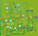
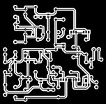
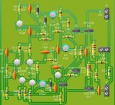
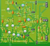
Now i can produce schematic and temporary boards
using LiveWire and Pcb Wizzard,
Not sophisticated, but something people can use while we wait the professional work from Taj.... these boards can help my group in the Orkut too.
VBE multiplier board not included, this is only an exercise, but for sure will work if etched.
The software trace the board automatically, something clever.
Official Art Director, for Boards and layouts is Taj.... a Dx Corporation Member that has a picture into the hall of fame in the headquarters.
I know the 2SC5200 size is not good...this is an exercise, but with wires we can build and will work, Dx amplifier can use wires to speaker, they use to be tested this way, if work in my home tests, under such crazy sittuation, will work also with this board.
regards,
Carlos
Attachments
Last edited:
This protects but limits the electrolitic condenser job
This avoids the voltage to exceed the electrolitic condenser maximum insulation voltage, and this may happens in several cases... so, you can use 16 volts small condenser in the place to use the normal (better ) rail to rail electrolitic condenser.
Distortions, clipping may produce DC at the output line, and this will cross R13 that will limit the current in something around 2 miliamps i think.
If your NPN or PNP driver result damaged, then you gonna have rail voltage at the output line, also happens if NPN and PNP output damaged...what happens?
The rail voltage (35V) cross R13 and charge electrolitic condenser C7... well, 35 volts will destroy the electrolitic condenser that will explode, the diode will be there, in the schematic case, to protect, draining the voltage and resulting in 0.6 volts because diode zener properties and junction voltage drop ..will work if negative rail appear in the output line...if positive appear nothing will happens, the diode will not protect.
We need two diodes, in the reality, i think better is to use a rail to rail electrolitic condenser there in the place to use this diode, or these diodes in the case you install two, back to back.
Audio swing will also be present there, and the diodes will clip in 0.6 volts.
I do not like the idea, i think better without them, diodes use to generate noises and to detect radio frequency, use to create unstabilities too.
Just to talk a little, i was observing that, how i could do that mistake?..and nobody has perceived that, the revisers have not observed too.
Interesting, we use to make mistakes, and they can be watching us, or in front of our eyes for a very long time and we look at them without see them.
regards,
Carlos
Attachments
Last edited:
This satisfies me, i am a simple man, i do not need perfection
This software is enougth, do the job for us, we do not need to be studying how to use for weeks, 10 minutes is enought, it does automatically almost all we need, you have only to draw the schematic the same way (easier) you do with Multisim, Workbench and others.
You click in "produce boards" and ready...this is clever, this way we do not turn slaves from the software, the hell thing works for us to simplify our lives, instead of complicate our lives.
regards,
Carlos
Attachments
Last edited:
- Status
- This old topic is closed. If you want to reopen this topic, contact a moderator using the "Report Post" button.
- Home
- Amplifiers
- Solid State
- Dx Blame ES .... based into the Blameless, i am trying a new amplifier